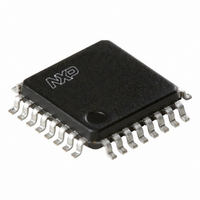
PCK946BD,157 NXP Semiconductors, PCK946BD,157 Datasheet

PCK946BD,157
Specifications of PCK946BD,157
935281249157
PCK946BD
Available stocks
Related parts for PCK946BD,157
PCK946BD,157 Summary of contents
Page 1
PCK946 Low voltage CMOS clock driver Rev. 01 — 13 December 2005 1. General description The PCK946 is a low voltage CMOS clock buffer. The 10 outputs can be configured into a standard fan-out ...
Page 2
Philips Semiconductors 3. Ordering information Table 1: Type number PCK946BD 4. Functional diagram Fig 1. Functional diagram of PCK946 9397 750 12296 Product data sheet Ordering information Package Name Description LQFP32 plastic low profile quad flat package; 32 leads; body ...
Page 3
Philips Semiconductors 5. Pinning information 5.1 Pinning Fig 2. Pin configuration for LQFP32 5.2 Pin description Table 2: Symbol DSELA, DSELB, DSELC GND GNDI MR/OE QA0, QA1, QA2 QB0, QB1, QB2 QC0, QC1, QC2, QC3 TCLK_SEL TCLK0, TCLK1 V CC ...
Page 4
Philips Semiconductors 6. Functional description 6.1 Function table Table 3: TCLK_SEL 0 1 Table 4: DSELn 0 1 Table 5: MR/ Limiting values Table 6: In accordance with the Absolute Maximum Rating System (IEC 60134). Symbol V ...
Page 5
Philips Semiconductors 8. Static characteristics Table 7: Static characteristics + 3.3 V amb CC Symbol Parameter V HIGH-state input voltage IH V LOW-state input voltage IL V HIGH-state output voltage OH V ...
Page 6
Philips Semiconductors 10. Application information 10.1 Driving transmission lines The PCK946 clock driver was designed to drive high speed signals in a terminated transmission line environment. To provide the optimum flexibility to the user the output drivers were designed to ...
Page 7
Philips Semiconductors At the load end the voltage will double, due to the near unity reflection coefficient will then increment towards the quiescent 3 steps separated by one round trip delay (in this case ...
Page 8
Philips Semiconductors 11. Package outline LQFP32: plastic low profile quad flat package; 32 leads; body 1 pin 1 index DIMENSIONS (mm are the original dimensions) ...
Page 9
Philips Semiconductors 12. Soldering 12.1 Introduction to soldering surface mount packages This text gives a very brief insight to a complex technology. A more in-depth account of soldering ICs can be found in our Data Handbook IC26; Integrated Circuit Packages ...
Page 10
Philips Semiconductors – smaller than 1.27 mm, the footprint longitudinal axis must be parallel to the transport direction of the printed-circuit board. The footprint must incorporate solder thieves at the downstream end. • For packages with leads on four sides, ...
Page 11
Philips Semiconductors [4] These packages are not suitable for wave soldering. On versions with the heatsink on the bottom side, the solder cannot penetrate between the printed-circuit board and the heatsink. On versions with the heatsink on the top side, ...
Page 12
Philips Semiconductors 15. Data sheet status [1] Level Data sheet status Product status I Objective data Development II Preliminary data Qualification III Product data Production [1] Please consult the most recently issued data sheet before initiating or completing a design. ...
Page 13
Philips Semiconductors 20. Contents 1 General description . . . . . . . . . . . . . . . . . . . . . . 1 2 Features . . . . . . . . ...


