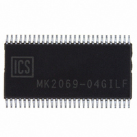
MK2069-04GILF IDT, Integrated Device Technology Inc, MK2069-04GILF Datasheet - Page 14

MK2069-04GILF
Manufacturer Part Number
MK2069-04GILF
Description
IC CLOCK SYNTHESIZER 56-TSSOP
Manufacturer
IDT, Integrated Device Technology Inc
Type
Clock Synchronizerr
Datasheet
1.MK2069-04GILF.pdf
(20 pages)
Specifications of MK2069-04GILF
Pll
Yes
Input
LVCMOS
Output
LVCMOS
Number Of Circuits
1
Ratio - Input:output
1:3
Differential - Input:output
No/No
Frequency - Max
160MHz
Divider/multiplier
Yes/No
Voltage - Supply
3.15 V ~ 3.45 V
Operating Temperature
-40°C ~ 85°C
Mounting Type
Surface Mount
Package / Case
56-TSSOP
Frequency-max
160MHz
Number Of Elements
2
Supply Current
30mA
Pll Input Freq (min)
1KHz
Pll Input Freq (max)
170MHz
Operating Supply Voltage (typ)
3.3V
Operating Temp Range
-40C to 85C
Package Type
TSSOP
Output Frequency Range
0.5 to 160MHz
Operating Supply Voltage (min)
3.15V
Operating Supply Voltage (max)
3.45V
Operating Temperature Classification
Industrial
Pin Count
56
Lead Free Status / RoHS Status
Lead free / RoHS Compliant
Other names
800-1783
800-1783-5
800-1783
800-1783-5
800-1783
Available stocks
Company
Part Number
Manufacturer
Quantity
Price
Company:
Part Number:
MK2069-04GILF
Manufacturer:
IDT Integrated Device Technolo
Quantity:
135
Company:
Part Number:
MK2069-04GILF
Manufacturer:
Vishay
Quantity:
2 489
Company:
Part Number:
MK2069-04GILFTR
Manufacturer:
TEMIC
Quantity:
36 603
Part Number:
MK2069-04GILFTR
Manufacturer:
ICS
Quantity:
20 000
Circuit Troubleshooting
1) IF TCLK or VCLK does not lock to ICLK
First check VCLK to ICLK. It is best to display and trigger the
scope with RCLK, especially if a non-integer VCXO PLL
multiplication ratio is used.
If VCLK is not locked to ICLK:
1.1) Ensure the proper ICLK input is selected.
1.2) Check RPV, RV, SV, FV Divider settings
1.3) Ensure ICLK is within lock range (within about 100 ppm
of the nominal input frequency, limited by pull range of the
external crystal). If in doubt, tweak the ICLK frequency up
and down to see if VCLK locks.
1.4) Ensure ICLK jitter is not excessive. If ICLK jitter is
excessive device may not lock. Also see item 2.1 below.
1.5) Clean the PCB. The VCXO PLL loop filter is very
sensitive to board leakage, especially when the VCXO PLL
phase detector frequency is in the low kHz. If organic solder
flux is used (most common today) scrub the PCB board with
detergent and water and then blow and bake dry. Inorganic
solder flux (Rosen core) requires solvent. See also section
3 below.
2) If There is Excessive Jitter on VCLK or TCLK
2.1) The problem may be an unstable input reference clock.
An unstable ICLK will not appear to jitter when ICLK is used
as the oscilloscope trigger source. In this condition, VCLK
and TCLK may appear to be unstable since the jitter from
ICLK (the trigger source) has been removed by the trigger
circuit of the scope.
2.2) The instability may be caused by VCXO PLL loop filter
IDT® VCXO-BASED UNIVERSAL CLOCK TRANSLATOR
MK2069-04
VCXO-BASED UNIVERSAL CLOCK TRANSLATOR
14
leakage. Refer to item 1.5 above.
2.3) VCLK and TCLK jitter can also be caused by poor
power supply decoupling. Ensure a bulk decoupling
capacitor is in place.
2.4) Ensure that the VCXO PLL loop bandwidth is
sufficiently low. It should be at least 1/20th of the phase
detector frequency.
2.5) Ensure that the VCXO PLL loop damping is sufficient.
If should be at least 0.7, preferably 1.0 or higher.
2.6) Ensure that the 2nd pole in the VCXO PLL loop filter is
set sufficiently. In general, C
C
instability may occur. If C
modulation by the charge correction pulses may occur.
3) If There is Excessive Input to Output Skew
3.1) TCLK should track VCLK. The rising edge of TCLK
should be within a few nanoseconds of VCLK.
3.1) VCLK should track RCLK. The rising edge of VCLK
should be within 5-10 nsec of RCLK (VCLK leads).
3.3) The biggest cause of input to output skew is VCXO PLL
loop filter leakage. Skew is best observed by comparing
ICLK to RCLK. When no leakage is present the rising edge
of RCLK should lag the rising edge of ICLK by about 10
or cause the loop to not lock. Refer to item 1.5, above.
3.4) Another way to view the loop filter leakage is to observe
LDR pin. Use RCLK as the scope trigger. LDR will produce
a negative pulse equal in length to the charge pump pulse.
3.5) Filter leakage can also be caused by the use of
improper loop capacitors. Refer to the section titled ‘Loop
Filter Capacitor Type’ on page 9.
sec. Loop filter leakage can greatly increase this lag time
P
is too high, passband peaking will occur and loop
P
is set too low, excessive VCXO
P
should be equal to C
VCXO AND SYNTHESIZER
MK2069-04
REV J 051310
S
/20. If


