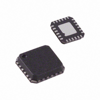
ADF4360-8BCPZ Analog Devices Inc, ADF4360-8BCPZ Datasheet - Page 18

ADF4360-8BCPZ
Manufacturer Part Number
ADF4360-8BCPZ
Description
IC SYNTHESIZER VCO 24-LFCSP
Manufacturer
Analog Devices Inc
Type
Fanout Distribution, Integer N Synthesizer (RF)r
Datasheet
1.ADF4360-8BCPZRL7.pdf
(24 pages)
Specifications of ADF4360-8BCPZ
Pll
Yes
Input
CMOS
Output
Clock
Number Of Circuits
1
Ratio - Input:output
1:2
Differential - Input:output
No/No
Frequency - Max
400MHz
Divider/multiplier
Yes/No
Voltage - Supply
3 V ~ 3.6 V
Operating Temperature
-40°C ~ 85°C
Mounting Type
Surface Mount
Package / Case
24-LFCSP
Frequency-max
400MHz
Pll Type
Frequency Synthesis
Frequency
400MHz
Supply Current
5mA
Supply Voltage Range
3V To 3.6V
Digital Ic Case Style
LFCSP
No. Of Pins
24
Operating Temperature Range
-40°C To +85°C
Lead Free Status / RoHS Status
Lead free / RoHS Compliant
For Use With
EVAL-ADF4360-8EBZ1 - BOARD EVALUATION FOR ADF4360-8
Lead Free Status / RoHS Status
Lead free / RoHS Compliant, Lead free / RoHS Compliant
Available stocks
Company
Part Number
Manufacturer
Quantity
Price
Company:
Part Number:
ADF4360-8BCPZ
Manufacturer:
FUJ
Quantity:
2 557
Part Number:
ADF4360-8BCPZ
Manufacturer:
ADI/亚德诺
Quantity:
20 000
Company:
Part Number:
ADF4360-8BCPZRL7
Manufacturer:
HISILICON
Quantity:
101
Part Number:
ADF4360-8BCPZRL7
Manufacturer:
ADI/亚德诺
Quantity:
20 000
ADF4360-8
Hardware Power-Up/Power-Down
If the part is powered down via the hardware (using the CE pin)
and powered up again without any change to the N counter
register during power-down, the part locks at the correct fre-
quency, because the part is already in the correct frequency
band. The lock time depends on the value of capacitance on the
C
capacitance of 440 nF on this pin enables lock times of <600 µs.
The N counter value cannot be changed while the part is in
power-down, since the part may not lock to the correct
frequency on power-up. If it is updated, the correct program-
ming sequence for the part after power-up is the R counter
latch, followed by the control latch, and finally the N counter
latch, with the required interval between the control latch and N
counter latch, as described in the Initial Power-Up section.
N
pin, which is <15 ms for 10 µF capacitance. The smaller
Rev. A | Page 18 of 24
Software Power-Up/Power-Down
If the part is powered down via the software (using the control
latch) and powered up again without any change to the N
counter latch during power-down, the part locks at the correct
frequency, because the part is already in the correct frequency
band. The lock time depends on the value of capacitance on the
C
capacitance of 440 nF on this pin enables lock times of <600 µs.
The N counter value cannot be changed while the part is in
power-down, because the part may not lock to the correct
frequency on power-up. If it is updated, the correct program-
ming sequence for the part after power-up is to the R counter
latch, followed by the control latch, and finally the N counter
latch, with the required interval between the control latch and N
counter latch, as described in the Initial Power-Up section.
N
pin, which is <15 ms for 10 µF capacitance. The smaller


