1-1740198-2 TE Connectivity, 1-1740198-2 Datasheet
1-1740198-2
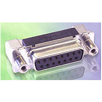
Specifications of 1-1740198-2
Available stocks


Related parts for 1-1740198-2


1-1740198-2 Summary of contents
Page 1
... APPLICABLE DOCUMENTS The following AMP- respective TYCO – documents and DIN - norm form a part of this specification to the extent specified herein. In the events of conflict between the requirements of this specification and the product drawing, the product drawing shall take precedence. In the event of conflict between the requirements of this specification and the referenced documents, this specification shall take precedence ...
Page 2
... Performance and Test Description The product is designed to meet the electrical, mechanical and environmental performance requirements specified in Figure 1. All tests are performed at ambient environmental conditions per IEC 60512 unless otherwise specified. 3.5 Test Requirements and Procedures Test Description Examination of product. Termination resistance, dry ...
Page 3
... Note: Grounding indents are on the pin side Minimum 30 N for pin and min for receptacle contact Environmental Inspections See Note See Note 108-94000 AMP Spec 109-27. Mate and unmate assemblies for 200 cycles for 0,8 µm gold plated at a maximum rate of 200 cycles per hour ...
Page 4
... Figure 108-94000 IEC 60068 – 2 – Subject mated connectors to temperature life at 105°C for 500 hours. IEC 60068 – 2 -60 Subject mated connectors to environmental class III for 20 days. Precondition connectors with 10 durability cycles. (Tyco spec. 109-201 / B ) 60068 – 2 – 20 1,8 1,3 ...
Page 5
... Test groups 2, 3 and 5 shall each consist of 5 mated connector pairs with no grounding indents, no mounting is required. Test group 1 shall consist of 4 mated connector pairs with grounding indents and shall be mounted on a printed circuit board. ...
Page 6
... Certification This product will be recognized under the Component Recognition Program of Underwirter’s Inc., Electrical File Number E-XXXXX LR-YYYYYY. NOTE To determinate the acceptable current carrying capacity for the percentage connector loading and wire gage indicated, use the Multiplication Factor (F) from the above chart and multiply it times the Base Rated Current for a single circuit at the maximum ambient operating temperature as shown in Figure 4A ...
Page 7
... Figure 108-94000 ...
Page 8
... Figure 108-94000 ...
Page 9
... Figure 108-94000 ...
Page 10
... Figure 108-94000 ...