1-747950-4 TE Connectivity, 1-747950-4 Datasheet
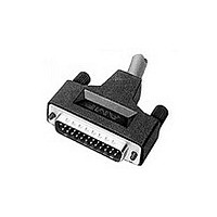
KIT,PLUG,37P,HDE,SHLD ENCLSRE

1-747950-4

Manufacturer Part Number
1-747950-4
Description
KIT,PLUG,37P,HDE,SHLD ENCLSRE
Manufacturer
TE Connectivity
Datasheets

Specifications of 1-747950-4

Product Type
Connector
Product Series
HDE-20 (IDC)
Wire/cable Type
Discrete Wire, Round Jacketed Cable
Termination Method To Wire/cable
Insulation Displacement Crimp (IDC)
Wire Insulation Diameter (mm [in])
1.52 [0.060]
Mating Connector Lock
With
Mating Connector Lock Type
Jackscrews
Shell Size
4
Shell Type
Front Metal Shell
Grounding Indents
With
Insulation Support
Yes
Grade
Standard
Enclosure Material
PVC
Jackscrew Material
Zinc Alloy
Color
Black
Shell Material
Steel
Shield Material
Steel
Shielded
Yes
Solder Tail Contact Plating
Tin over Nickel
Number Of Positions
37
Wire Range (mm² [awg])
0.05 - 0.15 [30-26]
Pre-assembled
No
Cable Insulation Diameter (mm [in])
8.59 – 14.28 [0.338 – 0.562]
Shell Plating
Tin
Shield Plating
Tin
Insert Material
Thermoplastic
Insert Flammability Rating
UL 94V-0
Cable Diameter (max.) (mm [in])
14.27 [0.562]
Preloaded
Yes
Contact Type
Pin
Contact Base Material
Phosphor Bronze
Contact Plating, Mating Area, Material
Gold (30)
Contact Size
20
Enclosure
With
Connector Style
Plug
Rohs/elv Compliance
RoHS compliant, ELV compliant
Lead Free Solder Processes
Not relevant for lead free process
Rohs/elv Compliance History
Always was RoHS compliant
Packaging Method
Bulk

Available stocks

Company
Part Number
Manufacturer
Quantity
Price
Part Number:
1-747950-4
Manufacturer:
TE Connectivity AMP Connectors
Quantity:
457
1.
1.1.
1.2.
2.
2.1.
3.
3.1.
3.2.
3.3.
©2011 Tyco Electronics Corporation,
a TE Connectivity Ltd. Company
All Rights Reserved
TE logo is a trademark.
SCOPE
Content
This specification covers the performance, tests and quality requirements for AMPLIMITE* HDE
connector with (removable) insulation displacement (and "F" crimp) contacts in a one piece plastic
housing, with or without a metal shell. The assemblies can contain a combination of insulation
displacement and "F" crimp HDE contacts.
Qualification
When tests are performed on the subject product line, the procedures specified in 109-Series Test
Specifications shall be used. All inspections shall be performed using the applicable inspection plan
and product drawing.
APPLICABLE DOCUMENTS
The following documents form a part of this specification to the extent specified herein. In the event of
conflict between the requirements of this specification and the product drawing, the product drawing
shall take precedence. In the event of conflict between the requirements of this specification and the
referenced documents, this specification shall take precedence.
TE Connectivity (TE) Documents
A.
B.
C.
D.
E.
REQUIREMENTS
Design and Construction
Product shall be of the design, construction and physical dimensions specified on the applicable
product drawing.
Materials
A.
B.
Ratings
A.
B.
C.
109-1:
109 Series:
114-40002:
114-40003:
501-115:
Contact: Phosphor bronze, gold on mating end, tin plated on crimp end.
Housing: Glass filled polyester, black, UL 94V-0
Voltage: 250 vac
Current: Fully loaded and energized connectors
1.
2.
3.
4.
5.
6.
Temperature: -55° to 105°C
30-28
26
24
22
20
18 F crimp 3.7 A
Product
Specification
AMPLIMITE* HDE-20 Insulation Displacement Connector
| Indicates Change
*Trademark
General Requirements for Test Specifications
Test Specifications as indicated in Figure 1.
Application Specification, Contact, AMPLIMITE, HDE-20
Application Specification, Contact, AMPLIMITE, HDE-20,"F" Crimp
Test Report
AWG 1.0 A
AWG 1.5 A
AWG 2.0 A
AWG 2.4 A
AWG 3.0 A
Other products, logos, and company names might be trademarks of their respective owners.
For latest revision, visit out website at www.te.com/documents
For Regional Customer service, visit our website at www.te.com
108-40011
11 Mar 11 Rev C
1 of 7
LOC B

Related parts for 1-747950-4

1-747950-4 Summary of contents

Page 1

... The assemblies can contain a combination of insulation displacement and "F" crimp HDE contacts. 1.2. Qualification When tests are performed on the subject product line, the procedures specified in 109-Series Test Specifications shall be used. All inspections shall be performed using the applicable inspection plan and product drawing. 2. ...

Page 2

... Performance and Test Description The product is designed to meet the electrical, mechanical and environmental performance requirements specified in Figure 1. All tests are performed at ambient temperature unless otherwise specified. 3.5. Test Requirements and Procedures Summary Test Description Examination of Product Termination Resistance, Dry Circuit ...

Page 3

... Microinches Cycles Cold Flash 100 30 Gold 500 Subject mated connectors to 5 cycles between -55° and 105° C; Test Specification 109-22. Subject mated connectors to 10 humidity-temperature cycles between 25° and 65° 95% RH; Test Specification 109-23-4, cond B. Electrical measurements shall be made within 5 hours of removal of samples from chamber ...

Page 4

... Discontinuities shall not be measured for this test group. (c) Numbers indicate sequence in which tests are performed. Rev C Requirement See note (a). Figure 1 (end Figure 2 108-40011 Procedure Subject mated connectors to temperature life; Test Specification 109-43, test level 10 (105° ), test duration C (500 hours). Test Group ( ( Test Sequence ( ...

Page 5

... Contacts in these groups shall be terminated as follows: 20 and 22 AWG to the number 3 slot, 24 and 26 AWG to the number 2 slot, and 30 AWG to the number 1 slot. Test group 5 shall consist of 25 position, all plastic plugs and receptacles; gold flash duplex plated contacts. Contacts in group 5 shall be terminated as follows: 22 AWG to the number 3 slot, 22 and 26 AWG to the number 2 slot, 26 and 30 AWG to the number 1 slot ...

Page 6

... Receptacle connector to be mounted on vibration fixture unless otherwise NOTE specified. Rev C Figure 3 Mounting and Clamping Locations for Vibration and Physical Shock 108-40011 ...

Page 7

... Resistance and Temperature Measurement Points 1. Gage material: 100-97 NOTES 2. Heat treat to Rc 68-70 3. This gage is for contact size 20 4. Pin to comply with MS 3197 5. Finish: 6-10 microinches rms Rev C Figure 4 Gage TE P .0000 A 27280-8 .0410 - .0001 + .0001 B 27280-7 .0390 - .0000 Figure 5 108-40011 ...

Related keywords