DS1110S-100 Maxim Integrated Products, DS1110S-100 Datasheet
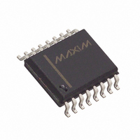
DELAY LINE 5V 10TAP 100NS 16SOIC

DS1110S-100

Manufacturer Part Number
DS1110S-100
Description
DELAY LINE 5V 10TAP 100NS 16SOIC
Manufacturer
Maxim Integrated Products
Datasheet

Specifications of DS1110S-100

Number Of Taps/steps
10
Function
Tapped
Delay To 1st Tap
10nS
Tap Increment
10nS
Available Total Delays
100ns
Voltage - Supply
4.75 V ~ 5.25 V
Operating Temperature
-40°C ~ 85°C
Mounting Type
Surface Mount
Package / Case
16-SOIC (0.300", 7.5mm Width)
Lead Free Status / RoHS Status
Contains lead / RoHS non-compliant
Number Of Independent Delays
-

Available stocks

Company
Part Number
Manufacturer
Quantity
Price
Part Number:
DS1110S-100+
Manufacturer:
Maxim
Quantity:
50
The DS1110 delay line is an improved replacement for
the DS1010. It has ten equally spaced taps providing
delays from 5ns to 500ns. The devices are offered in a
standard 16-pin SO or 14-pin TSSOP. The DS1110 series
delay lines provide a nominal accuracy of ±5% or ±2ns,
whichever is greater, at 5V and +25°C. The DS1110
reproduces the input logic state at the tap 10 output after
a fixed delay as specified by the dash number extension
of the part number. The DS1110 is designed to produce
both leading- and trailing-edge delays with equal preci-
sion. Each tap is capable of driving up to ten 74LS type
loads. Dallas Semiconductor can customize standard
products to meet special needs.
Rev 1; 11/03
For pricing, delivery, and ordering information, please contact Maxim/Dallas Direct! at
1-888-629-4642, or visit Maxim’s website at www.maxim-ic.com.
Pin Configurations continued at end of data sheet.
Communications Equipment
Medical Devices
Automated Test Equipment
PC Peripheral Devices
TOP VIEW
TAP2
TAP4
TAP6
TAP8
GND
N.C.
IN
1
4
5
6
7
2
3
General Description
DS1110E
Pin Configurations
TSSOP
Applications
14
13
12
11
10
8
9
_____________________________________________ Maxim Integrated Products
V
TAP1
TAP3
TAP5
TAP7
TAP9
TAP10
CC
10-Tap Silicon Delay Line
♦ All-Silicon, 5V, 10-Tap Delay Line
♦ Improved, Drop-In Replacement for the DS1010
♦ 10 Taps Equally Spaced
♦ Delays are Stable and Precise
♦ Leading- and Trailing-Edge Accuracy
♦ Delay Tolerance ±5% or ±2ns, whichever is
♦ Economical
♦ Auto-Insertable, Low Profile
♦ Low-Power CMOS
♦ TTL/CMOS Compatible
♦ Vapor Phase, IR, and Wave Solderable
♦ Fast-Turn Prototypes
♦ Delays Specified Over Commercial and Industrial
♦ Custom Delays Available
♦ Standard 16-Pin SO or 14-Pin TSSOP
Selector Guide appears at end of data sheet.
DS1110E-XXX
DS1110S-XXX
Greater, at 5V and +25°C
Temperature Ranges
PART
-40°C to +85°C
-40°C to +85°C
TEMP RANGE
Ordering Information
PIN-PACKAGE
14 TSSOP
16 SO
Features
1

Related parts for DS1110S-100

DS1110S-100 Summary of contents

Page 1

... TTL/CMOS Compatible Applications ♦ Vapor Phase, IR, and Wave Solderable ♦ Fast-Turn Prototypes ♦ Delays Specified Over Commercial and Industrial Temperature Ranges ♦ Custom Delays Available ♦ Standard 16-Pin SO or 14-Pin TSSOP PART DS1110E-XXX DS1110S-XXX TAP1 12 TAP3 Selector Guide appears at end of data sheet. 11 ...

Page 2

Silicon Delay Line ABSOLUTE MAXIMUM RATINGS Voltage on Any Pin Relative to Ground .................-0.5V to +6.0V Operating Temperature Range ...........................-40°C to +85°C Stresses beyond those listed under “Absolute Maximum Ratings” may cause permanent damage to the device. These are ...

Page 3

CAPACITANCE (T = +25°C.) A PARAMETER SYMBOL Input Capacitance Note 1: All voltages are referenced to ground. Note 2: Measured with outputs open. Note 3: Initial tolerances are ± with respect to the nominal value at +25°C and V Note ...

Page 4

Silicon Delay Line (V = 5.0V +25°C, unless otherwise noted DS1110-500 DELAY vs. TAP 500 FALLING EDGE 450 400 350 300 250 200 150 100 TAP DS1110-500 TAP ...

Page 5

Detailed Description The DS1110 delay line is an improved replacement for the DS1010. It has ten equally spaced taps providing delays from 5ns to 500ns. The devices are offered in a standard 16-pin SO or 14-pin TSSOP. The DS1110 series ...

Page 6

Silicon Delay Line Period: The time elapsed between the leading edge of the first pulse and the leading edge of the following pulse. t (Pulse Width): The elapsed time on the pulse WI between the 1.5V point on the ...

Page 7

... TOTAL PIN- DELAY PART PACKAGE (ns)* 14 TSSOP 50 DS1110S-50 14 TSSOP 60 DS1110S-60 14 TSSOP 75 DS1110S-75 14 TSSOP 80 DS1110S-80 14 TSSOP 100 DS1110S-100 14 TSSOP 125 DS1110S-125 14 TSSOP 150 DS1110S-150 14 TSSOP 175 DS1110S-175 14 TSSOP 200 DS1110S-200 14 TSSOP 250 DS1110S-250 14 TSSOP 300 DS1110S-300 14 TSSOP 350 ...

Page 8

... Silicon Delay Line Pin Configurations (continued) TOP VIEW IN1 1 N.C. 2 N.C. 3 TAP2 4 DS1110S TAP4 5 TAP6 6 TAP8 7 GND 8 SO (300mil) Maxim cannot assume responsibility for use of any circuitry other than circuitry entirely embodied in a Maxim product. No circuit patent licenses are implied. Maxim reserves the right to change the circuitry and specifications without notice at any time. ...

Related keywords