DS1013-100 Maxim Integrated Products, DS1013-100 Datasheet
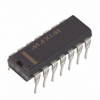
DELAY LINE 3TAP 100NS MAX 14-DIP

DS1013-100

Manufacturer Part Number
DS1013-100
Description
DELAY LINE 3TAP 100NS MAX 14-DIP
Manufacturer
Maxim Integrated Products
Datasheet

Specifications of DS1013-100

Function
Multiple
Delay To 1st Tap
100nS
Available Total Delays
100, 100, 100ns
Number Of Independent Delays
3
Voltage - Supply
4.75 V ~ 5.25 V
Operating Temperature
0°C ~ 70°C
Mounting Type
Through Hole
Package / Case
14-DIP (0.300", 7.62mm)
Lead Free Status / RoHS Status
Contains lead / RoHS non-compliant
Number Of Taps/steps
-
Tap Increment
-

Available stocks

Company
Part Number
Manufacturer
Quantity
Price
Part Number:
DS1013-100
Manufacturer:
TI
Quantity:
14 000
FEATURES
DESCRIPTION
The DS1013 series of delay lines has three independent logic buffered delays in a single package. The
devices are offered in a standard 14-pin DIP which is pin-compatible with hybrid delay lines. Alternative
8-pin DIP and surface mount packages are available which save PC board area. Since the DS1013
products are an all silicon solution, better economy is achieved when compared to older methods using
hybrid techniques. The DS1013 series delay lines provide a nominal accuracy of 2ns for delay times
ranging from 10 ns to 60 ns, increasing to 5% for delays of 150 ns and longer. The DS1013 delay line
reproduces the input logic state at the output after a fixed delay as specified by the dash number extension
of the part number. The DS1013 is designed to reproduce both leading and trailing edges with equal
precision. Each output is capable of driving up to 10 74LS loads. Dallas Semiconductor can customize
standard products to meet special needs. For special requests and rapid delivery, call (972) 371–4348.
www.dalsemi.com
All-silicon time delay
3 independent buffered delays
Delay tolerance ±2ns for -10 through –60
Stable and precise over temperature and
voltage range
Leading and trailing edge accuracy
Economical
Auto-insertable, low profile
Standard 14-pin DIP, 8-pin DIP, or 16-pin
SOIC
Low-power CMOS
TTL/CMOS-compatible
Vapor phase, IR and wave solderable
Custom delays available
Quick turn prototypes
Extended temperature ranges available
1 of 6
DS1013 14-pin DIP (300-mil)
GND
See Mech. Drawings Section
IN 1
IN 2
IN 3
NC
NC
NC
PIN ASSIGNMENT
PIN DESCRIPTION
IN 1, IN 2, IN 3
OUT 1, OUT 2, OUT 3 - Outputs
GND
V
NC
CC
1
2
3
4
5
6
7
3-in-1 Silicon Delay Line
DS1013M 8-pin DIP (300-mil)
11
10
14
13
12
See Mech. Drawings Section
9
8
GND
IN 1
IN 2
IN 3
NC
OUT 1
V
NC
NC
OUT 2
OUT 3
CC
1
2
3
4
See Mech. Drawings Section
GND
IN 2
IN 3
IN 1
- Inputs
- Ground
- +5 Volts
- No Connection
NC
NC
NC
NC
DS1013S 16-pin SOIC
8
7
6
5
1
2
6
7
3
4
5
8
(300-mil)
V
OUT 1
OUT 2
OUT 3
CC
DS1013
16
15
14
13
12
11
10
9
V
NC
NC
OUT 1
OUT 2
NC
OUT 3
NC
111799
CC

Related parts for DS1013-100

DS1013-100 Summary of contents

Page 1

... The DS1013 series delay lines provide a nominal accuracy of 2ns for delay times ranging from ns, increasing to 5% for delays of 150 ns and longer. The DS1013 delay line reproduces the input logic state at the output after a fixed delay as specified by the dash number extension of the part number ...

Page 2

... PART NUMBER DELAY TABLE (t PART NO. DS1013-10 DS1013-12 DS1013-15 DS1013-20 DS1013-25 DS1013-30 DS1013-35 DS1013-40 DS1013-45 DS1013-50 DS1013-60 DS1013-70* DS1013-75* DS1013-80* DS1013-100* DS1013-150** DS1013-200** Custom delays available * ±3% tolerance ** ±5% tolerance , t ) Table 1 PHL PLH DELAY PER OUTPUT (ns) 10/10/10 12/12/12 15/15/15 20/20/20 25/25/25 30/30/30 ...

Page 3

... TIMING DIAGRAM: SILICON DELAY LINE Figure 2 TEST CIRCUIT Figure DS1013 ...

Page 4

... MIN t 100 PLH t PLH t PHL t PU Period MIN (0°C to 70° 5.0V ± 5%) CC TYP MAX UNITS 5.00 5. 0.5 CC 0.8 V 1.0 µ -1 25° ± 5 TYP MAX UNITS ns Table 1 ns Table 1 ns 100 TYP MAX UNITS DS1013 NOTES NOTES 25°C) NOTES ...

Page 5

... Delay, Falling): The elapsed time between the 1.5V point on the trailing edge of the input PHL pulse and the 1.5V point on the trailing edge of any tap output pulse DS1013 ...

Page 6

... TEST SETUP DESCRIPTION Figure 3 illustrates the hardware configuration used for measuring the timing parameters on the DS1013. The input waveform is produced by a precision pulse generator under software control. Time delays are measured by a time interval counter (20 ps resolution) connected between each input and corresponding output ...

Related keywords