ICM7555CBAZ Intersil, ICM7555CBAZ Datasheet
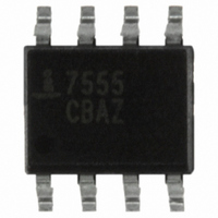
IC TIMER RC GEN PURP CMOS 8SOIC

ICM7555CBAZ

Manufacturer Part Number
ICM7555CBAZ
Description
IC TIMER RC GEN PURP CMOS 8SOIC
Manufacturer
Intersil
Type
555 Type, Timer/Oscillator (Single)r
Datasheet

Specifications of ICM7555CBAZ

Frequency
1MHz
Voltage - Supply
2 V ~ 18 V
Current - Supply
60µA
Operating Temperature
0°C ~ 70°C
Package / Case
8-SOIC (3.9mm Width)
Lead Free Status / RoHS Status
Lead free / RoHS Compliant
Count
-

Available stocks

Company
Part Number
Manufacturer
Quantity
Price
Part Number:
ICM7555CBAZ
Manufacturer:
INTERSIL
Quantity:
17
Part Number:
ICM7555CBAZ
Manufacturer:
INTERSIL
Quantity:
20 000
Company:
Part Number:
ICM7555CBAZ
Quantity:
42
Part Number:
ICM7555CBAZ-T
Manufacturer:
Intersil
Quantity:
22 500
Part Number:
ICM7555CBAZ-T
Manufacturer:
INTERSIL
Quantity:
20 000
Company:
Part Number:
ICM7555CBAZ-T
Quantity:
83
Part Number:
ICM7555CBAZT
Manufacturer:
STM
Quantity:
3 179
General Purpose Timers
The ICM7555 and ICM7556 are CMOS RC timers providing
significantly improved performance over the standard
SE/NE 555/6 and 355 timers, while at the same time being
direct replacements for those devices in most applications.
Improved parameters include low supply current, wide
operating supply voltage range, low THRESHOLD,
TRIGGER and RESET currents, no crowbarring of the
supply current during output transitions, higher frequency
performance and no requirement to decouple CONTROL
VOLTAGE for stable operation.
Specifically, the ICM7555 and ICM7556 are stable
controllers capable of producing accurate time delays or
frequencies. The ICM7556 is a dual ICM7555, with the two
timers operating independently of each other, sharing only
V+ and GND. In the one shot mode, the pulse width of each
circuit is precisely controlled by one external resistor and
capacitor. For astable operation as an oscillator, the free
running frequency and the duty cycle are both accurately
controlled by two external resistors and one capacitor. Unlike
the regular bipolar SE/NE 555/6 devices, the CONTROL
VOLTAGE terminal need not be decoupled with a capacitor.
The circuits are triggered and reset on falling (negative)
waveforms, and the output inverter can source or sink
currents large enough to drive TTL loads, or provide minimal
offsets to drive CMOS loads.
Pinouts
TRIGGER
OUTPUT
RESET
GND
ICM7555 (8 LD PDIP, SOIC)
1
2
3
4
®
1
TOP VIEW
Data Sheet
8
7
6
5
V
DISCHARGE
THRESHOLD
CONTROL
VOLTAGE
DD
1-888-INTERSIL or 1-888-468-3774
CAUTION: These devices are sensitive to electrostatic discharge; follow proper IC Handling Procedures.
Features
• Exact Equivalent in Most Cases for SE/NE555/556 or
• Low Supply Current
• Extremely Low Input Currents . . . . . . . . . . . . . . . . . 20pA
• High Speed Operation . . . . . . . . . . . . . . . . . . . . . . . 1MHz
• Guaranteed Supply Voltage Range . . . . . . . . . 2V to 18V
• Temperature Stability . . . . . . . . . . . . 0.005%/°C at +25°C
• Normal Reset Function - No Crowbarring of Supply During
• Can be Used with Higher Impedance Timing Elements
• Timing from Microseconds through Hours
• Operates in Both Astable and Monostable Modes
• Adjustable Duty Cycle
• High Output Source/Sink Driver can Drive TTL/CMOS
• Outputs have Very Low Offsets, HI and LO
• Pb-Free Plus Anneal Available (RoHS Compliant)
Applications
• Precision Timing
• Pulse Generation
• Sequential Timing
• Time Delay Generation
• Pulse Width Modulation
• Pulse Position Modulation
• Missing Pulse Detector
TLC555/556
- ICM7555 . . . . . . . . . . . . . . . . . . . . . . . . . . . . . . . . 60μA
- ICM7556 . . . . . . . . . . . . . . . . . . . . . . . . . . . . . . . 120μA
Output Transition
than Regular 555/6 for Longer RC Time Constants
DISCHARGE
Copyright © Intersil Americas Inc. 2002, 2004, 2005, 2006. All Rights Reserved
August 24, 2006
CONTROL
VOLTAGE
TRIGGER
THRESH-
OUTPUT
All other trademarks mentioned are the property of their respective owners.
RESET
ICM7556 (14 LD PDIP, CERDIP)
GND
OLD
|
Intersil (and design) is a registered trademark of Intersil Americas Inc.
1
2
3
4
5
6
7
TOP VIEW
ICM7555, ICM7556
14
13
12
10
11
9
8
V
DISCHARGE
THRESHOLD
CONTROL
VOLTAGE
RESET
OUTPUT
TRIGGER
DD
FN2867.9

Related parts for ICM7555CBAZ

ICM7555CBAZ Summary of contents

Page 1

... CAUTION: These devices are sensitive to electrostatic discharge; follow proper IC Handling Procedures. | 1-888-INTERSIL or 1-888-468-3774 Intersil (and design registered trademark of Intersil Americas Inc. Copyright © Intersil Americas Inc. 2002, 2004, 2005, 2006. All Rights Reserved All other trademarks mentioned are the property of their respective owners. ICM7555, ICM7556 FN2867.9 ...

Page 2

... Ordering Information PART NUMBER PART MARKING ICM7555CBA 7555 CBA ICM7555CBA-T 7555 CBA ICM7555CBAZ (Note) 7555 CBAZ ICM7555CBAZ-T (Note) 7555 CBAZ ICM7555IBA 7555 IBA ICM7555IBAT 7555 IBA ICM7555IBAZ (Note) 7555 IBAZ ICM7555IBAZ-T (Note) 7555 IBAZ ICM7555IPA 7555 IPA ICM7555IPAZ (Note) 7555 IPAZ ...

Page 3

Absolute Maximum Ratings Supply Voltage ...

Page 4

Electrical Specifications Applies to ICM7555 and ICM7556, unless otherwise specified (Continued) PARAMETER SYMBOL Reset Voltage V RST Reset Current I RST Discharge Leakage I DIS Output Voltage Discharge Output Voltage V DIS Supply Voltage (Note 3) ...

Page 5

Schematic Diagram P P THRESHOLD N N CONTROL VOLTAGE TRIGGER R = 100kΩ ±20% (TYP) Application Information General The ICM7555 and ICM7556 devices are, in most instances, direct replacements for the NE/SE 555/6 devices. However possible to effect ...

Page 6

OUTPUT FIGURE 2B. ALTERNATE ASTABLE CONFIGURATION OUTPUT DRIVE CAPABILITY The output driver consists of a CMOS inverter capable of driving most logic families including CMOS and TTL. As such, ...

Page 7

Typical Performance Curves 1200 1100 T = 25°C A 1000 900 800 700 600 500 400 DD 300 200 100 LOWEST VOLTAGE LEVEL OF TRIGGER PULSE (%V ...

Page 8

Typical Performance Curves 25° 10kΩ 0.1μ 0.1 1.0 SUPPLY VOLTAGE (V) FIGURE 10. NORMALIZED FREQUENCY STABILITY IN THE ASTABLE MODE ...

Page 9

Small Outline Plastic Packages (SOIC) N INDEX 0.25(0.010) H AREA E - SEATING PLANE - -C- α 0.10(0.004) 0.25(0.010 NOTES: 1. Symbols are defined in the ...

Page 10

Dual-In-Line Plastic Packages (PDIP INDEX N/2 AREA -B- -A- D BASE PLANE -C- SEATING PLANE 0.010 (0.25 NOTES: 1. Controlling Dimensions: INCH. In case of conflict between ...

Page 11

Dual-In-Line Plastic Packages (PDIP INDEX N/2 AREA -B- -A- D BASE PLANE -C- SEATING PLANE 0.010 (0.25 NOTES: 1. Controlling Dimensions: INCH. In case of conflict between ...

Page 12

... Accordingly, the reader is cautioned to verify that data sheets are current before placing orders. Information furnished by Intersil is believed to be accurate and reliable. However, no responsibility is assumed by Intersil or its subsidiaries for its use; nor for any infringements of patents or other rights of third parties which may result from its use ...

Related keywords