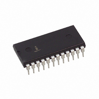
CP82C54-10Z Intersil, CP82C54-10Z Datasheet

CP82C54-10Z
Specifications of CP82C54-10Z
Available stocks
Related parts for CP82C54-10Z
CP82C54-10Z Summary of contents
Page 1
... All other trademarks mentioned are the property of their respective owners. 82C54 FN2970 + + +125 82C54 (PLCC/CLCC) TOP VIEW CLK2 10 20 OUT GATE Intersil (and design registered trademark of Intersil Americas Inc. Copyright © Intersil Americas Inc. 2003, 2005. All Rights Reserved ...
Page 2
... Ordering Information PART NUMBERS 8MHz 10MHz CP82C54 CP82C54-10 CP82C54Z (See Note) CP82C54-10Z (See Note) CP82C54-12Z (See Note) CS82C54* CS82C54-10* CS82C54Z* (See Note) CS82C54-10Z* (See Note) CS82C54-12Z* (See Note) ID82C54 - IP82C54 IP82C54-10 IP82C54Z (See Note) IP82C54-10Z (See Note) IS82C54* IS82C54-10* IS82C54Z (See Note) ...
Page 3
Absolute Maximum Ratings Supply Voltage . . . . . . . . . . . . . . . . . . . . . . . . . . . . . . . . . . . ...
Page 4
AC Electrical Specifications V CC SYMBOL PARAMETER READ CYCLE (1) TAR Address Stable Before RD (2) TSR CS Stable Before RD (3) TRA Address Hold Time After RD (4) TRR RD Pulse Width (5) TRD Data Delay from RD (6) ...
Page 5
Functional Diagram DATA/ BUS BUFFER RD READ/ WR WRITE LOGIC CONTROL WORD REGISTER Pin Description DIP PIN SYMBOL NUMBER TYPE I/O CLK 0 ...
Page 6
Functional Description General The 82C54 is a programmable interval timer/counter designed for use with microcomputer systems general purpose, multi-timing element that can be treated as an array of I/O ports in the system software. The 82C54 solves ...
Page 7
The status register, shown in the figure, when latched, contains the current contents of the Control Word Register and status of the output and null count flag. (See detailed explanation of the Read-Back command.) The actual counter is labeled CE ...
Page 8
Since the Control Word Register and the three Counters have separate addresses (selected by the A1, A0 inputs), and each Control Word specifies the Counter it applies to (SC0, SC1 bits), no special instruction sequence is required. Any programming sequence ...
Page 9
POSSIBLE PROGRAMMING SEQUENCE Control Word - Counter 1 Control Word - Counter 0 LSB of Count - Counter 1 Control Word - Counter 2 LSB of Count - Counter 0 MSB of Count - Counter 1 LSB of Count - ...
Page 10
D3 COUNT STATUS CNT 2 CNT 1 CNT ...
Page 11
COMMANDS ...
Page 12
If an initial count is written while GATE = 0, it will still be loaded on the next CLK pulse. When GATE goes high, OUT will go high N CLK pulses later; no CLK pulse is needed to load the ...
Page 13
MODE 2: RATE GENERATOR This Mode functions like a divide-by-N counter typically used to generate a Real Time Clock Interrupt. OUT will initially be high. When the initial count has decremented to 1, OUT goes low for one ...
Page 14
Mode 3 Is Implemented As Follows EVEN COUNTS - OUT is initially high. The initial count is loaded on one CLK pulse and then is decremented by two on succeeding CLK pulses. When the count expires, OUT changes value and ...
Page 15
Counter will be loaded with new count on the next CLK pulse and counting will continue from there LSB = 3 WR CLK GATE OUT ...
Page 16
Timing Waveforms DATA BUS DATA BUS RD 82C54 (9) tWA (11) tAW (10) tSW VALID (13) tWD (14) tDW (12) tWW FIGURE 17. WRITE tRA (3) tAR (1) ...
Page 17
Timing Waveforms (Continued) MODE WR CLK GATE OUT Burn-In Circuits MD82C54 (CERDIP VCC GND F10 6 ...
Page 18
Die Characteristics DIE DIMENSIONS: 129mils x 155mils x 19mils (3270µm x 3940µm x 483µm) Metallization Mask Layout CLK0 18 82C54 METALLIZATION: Type: Si-Al-Cu Thickness: Metal 1: 8kÅ ± 0.75kÅ Metal 2: 12kÅ ± 1.0kÅ GLASSIVATION: ...
Page 19
Dual-In-Line Plastic Packages (PDIP INDEX N/2 AREA -B- -A- D BASE PLANE -C- SEATING PLANE 0.010 (0.25 NOTES: 1. Controlling Dimensions: INCH. In case of conflict between ...
Page 20
Plastic Leaded Chip Carrier Packages (PLCC) 0.042 (1.07) 0.042 (1.07) 0.048 (1.22) 0.056 (1.42) PIN (1) IDENTIFIER 0.050 (1.27 0.020 (0.51) MAX 3 PLCS 0.026 (0.66) 0.032 (0.81) 0.045 (1.14) MIN VIEW “A” ...
Page 21
Ceramic Leadless Chip Carrier Packages (CLCC) 0.010 -E- 0.007 -H- - ...
Page 22
... Accordingly, the reader is cautioned to verify that data sheets are current before placing orders. Information furnished by Intersil is believed to be accurate and reliable. However, no responsibility is assumed by Intersil or its subsidiaries for its use; nor for any infringements of patents or other rights of third parties which may result from its use ...


