CP82C54-10 Intersil, CP82C54-10 Datasheet - Page 14
CP82C54-10
Manufacturer Part Number
CP82C54-10
Description
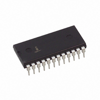
IC TIMER PROG CMOS 10MHZ 24-DIP
Manufacturer
Intersil
Type
Programmable Timerr
Datasheet
1.CS82C54Z96.pdf
(22 pages)
Specifications of CP82C54-10
Frequency
10MHz
Voltage - Supply
4.5 V ~ 5.5 V
Current - Supply
10mA
Operating Temperature
0°C ~ 70°C
Package / Case
24-DIP (0.600", 15.24mm)
Lead Free Status / RoHS Status
Contains lead / RoHS non-compliant
Count
-
Available stocks
Company
Part Number
Manufacturer
Quantity
Price
Company:

Part Number:
CP82C54-10
Manufacturer:
INTERSIL
Quantity:
600
Company:
Part Number:
CP82C54-10
Manufacturer:
INTERSIL
Quantity:
600
Company:
Part Number:
CP82C54-10
Manufacturer:
HARRIS
Quantity:
50
Company:
Part Number:
CP82C54-10
Manufacturer:
INTEL
Quantity:
5 510
Part Number:
CP82C54-10
Manufacturer:
HARRIS
Quantity:
20 000
Company:
Part Number:
CP82C54-10Z
Manufacturer:
INTERSIL
Quantity:
2 000


Mode 3 Is Implemented As Follows
EVEN COUNTS - OUT is initially high. The initial count is
loaded on one CLK pulse and then is decremented by two
on succeeding CLK pulses. When the count expires, OUT
changes value and the Counter is reloaded with the initial
count. The above process is repeated indefinitely.
ODD COUNTS - OUT is initially high. The initial count is loaded
on one CLK pulse, decremented by one on the next CLK pulse,
and then decremented by two on succeeding CLK pulses.
When the count expires, OUT goes low and the Counter is
reloaded with the initial count. The count is decremented by
three on the next CLK pulse, and then by two on succeeding
CLK pulses. When the count expires, OUT goes high again and
the Counter is reloaded with the initial count. The above
process is repeated indefinitely. So for odd counts, OUT will be
high for (N + 1)/2 counts and low for (N - 1)/2 counts.
MODE 4: SOFTWARE TRIGGERED MODE
OUT will be initially high. When the initial count expires, OUT
will go low for one CLK pulse then go high again. The
counting sequence is “Triggered” by writing the initial count.
GATE = 1 enables counting; GATE = 0 disables counting.
GATE has no effect on OUT.
After writing a Control Word and initial count, the Counter will
be loaded on the next CLK pulse. This CLK pulse does not
decrement the count, so for an initial count of N, OUT does not
strobe low until N + 1 CLK pulses after the initial count is
written.
If a new count is written during counting, it will be loaded on
the next CLK pulse and counting will continue from the new
count. If a two-byte count is written, the following happens:
This allows the sequence to be “retriggered” by software. OUT
strobes low N + 1 CLK pulses after the new count of N is
written.
1. Writing the first byte has no effect on counting.
2. Writing the second byte allows the new count to be
loaded on the next CLK pulse.
14
82C54
MODE 5: HARDWARE TRIGGERED STROBE
(RETRIGGERABLE)
OUT will initially be high. Counting is triggered by a rising
edge of GATE. When the initial count has expired, OUT will
go low for one CLK pulse and then go high again.
After writing the Control Word and initial count, the counter
will not be loaded until the CLK pulse after a trigger. This
CLK pulse does not decrement the count, so for an initial
count of N, OUT does not strobe low until N + 1 CLK pulses
after trigger.
A trigger results in the Counter being loaded with the initial
count on the next CLK pulse. The counting sequence is
triggerable. OUT will not strobe low for N + 1 CLK pulses
after any trigger GATE has no effect on OUT.
If a new count is written during counting, the current counting
sequence will not be affected. If a trigger occurs after the
new count is written but before the current count expires, the
GATE
GATE
GATE
OUT
CLK
OUT
OUT
CLK
CLK
WR
WR
WR
CW = 18
CW = 18
CW = 18
N
N
N
N
N
N
LSB = 3
LSB = 3
LSB = 3
N
N
N
FIGURE 13. MODE 4
N
N
N
0
3
0
3
0
3
LSB = 2
0
2
0
3
0
2
0
1
0
3
0
1
0
2
0
2
0
0
0
1
FF
FF
0
1
0
0
FF
FE
0
0
FF
FF
FF
FF
FF
FD
Related parts for CP82C54-10
Image
Part Number
Description
Manufacturer
Datasheet
Request
R

Part Number:
Description:
IC TIMER INTERVAL 10MHZ 24-PDIP
Manufacturer:
Intersil
Datasheet:
Part Number:
Description:
IC TIMER PROG CMOS 8MHZ 24-DIP
Manufacturer:
Intersil
Datasheet:
Part Number:
Description:
IC INTERFACE 5V 12.5MHZ 24-DIP
Manufacturer:
Intersil
Datasheet:
Part Number:
Description:
IC TIMER PROG CMOS 12MHZ 24DIP
Manufacturer:
Intersil
Datasheet:

Part Number:
Description:
Intersil Corporation [CMOS Serial Controller Interface]
Manufacturer:
Intersil Corporation
Datasheet:
Part Number:
Description:
Manufacturer:
Intersil Corporation
Datasheet:
Part Number:
Description:
357-036-542-201 CARDEDGE 36POS DL .156 BLK LOPRO
Manufacturer:
Intersil Corporation
Datasheet:
Part Number:
Description:
1024-Word x 4-Bit LSI Static RAM
Manufacturer:
Intersil Corporation
Datasheet:
Part Number:
Description:
General Purpose NPN Transistor Arrays FN341.4
Manufacturer:
Intersil Corporation
Datasheet:
Part Number:
Description:
CMOS 16-Bit Microprocessor
Manufacturer:
Intersil Corporation
Datasheet:
Part Number:
Description:
Manufacturer:
Intersil Corporation
Datasheet:
Part Number:
Description:
Manufacturer:
Intersil Corporation
Datasheet:
Part Number:
Description:
Manufacturer:
Intersil Corporation
Datasheet:
Part Number:
Description:
Manufacturer:
Intersil Corporation
Datasheet:
Part Number:
Description:
CMOS 6-Bit Latch and Decoder Memory Interfaces
Manufacturer:
Intersil Corporation
Datasheet: