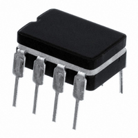
LM555J National Semiconductor, LM555J Datasheet - Page 7

LM555J
Manufacturer Part Number
LM555J
Description
IC TIMER HIGH TEMPERATURE 8-CDIP
Manufacturer
National Semiconductor
Type
555 Type, Timer/Oscillator (Single)r
Datasheet
1.LM555J.pdf
(12 pages)
Specifications of LM555J
Voltage - Supply
4.5 V ~ 16 V
Current - Supply
10mA
Operating Temperature
-55°C ~ 125°C
Package / Case
8-CDIP (0.300", 7.62mm)
Frequency
100kHz
Lead Free Status / RoHS Status
Contains lead / RoHS non-compliant
Count
-
Lead Free Status / Rohs Status
Not Compliant
Other names
*LM555J
Available stocks
Company
Part Number
Manufacturer
Quantity
Price
Part Number:
LM555J
Manufacturer:
NS/国半
Quantity:
20 000
Company:
Part Number:
LM555J/883Q
Manufacturer:
Fujitsu
Quantity:
1
Part Number:
LM555J/883Q
Manufacturer:
NS/国半
Quantity:
20 000
Applications Information
V
TIME = 20 µs/DIV. Middle Trace: Output 2V/Div.
R
C = 0.01 µF
PULSE WIDTH MODULATOR
When the timer is connected in the monostable mode and
triggered with a continuous pulse train, the output pulse
width can be modulated by a signal applied to pin 5. Figure
8 shows the circuit, and in Figure 9 are some waveform
examples.
V
TIME = 0.2 ms/DIV. Bottom Trace: Output Voltage 2V/Div.
R
C = 0.01 µF
PULSE POSITION MODULATOR
This application uses the timer connected for astable opera-
tion, as in Figure 10 , with a modulating signal again applied
to the control voltage terminal. The pulse position varies with
CC
CC
A
A
= 9.1 k
= 9.1 k
= 5V
= 5V
FIGURE 8. Pulse Width Modulator
FIGURE 9. Pulse Width Modulator
FIGURE 7. Frequency Divider
Top Trace: Input 4V/Div.
Top Trace: Modulation 1V/Div.
Bottom Trace: Capacitor 2V/Div.
(Continued)
DS007851-11
DS007851-12
DS007851-13
7
the modulating signal, since the threshold voltage and hence
the time delay is varied. Figure 11 shows the waveforms
generated for a triangle wave modulation signal.
V
TIME = 0.1 ms/DIV.
R
R
C = 0.01 µF
LINEAR RAMP
When the pullup resistor, R
placed by a constant current source, a linear ramp is gener-
ated. Figure 12 shows a circuit configuration that will perform
this function.
CC
A
B
= 3.9 k
= 3 k
= 5V
FIGURE 10. Pulse Position Modulator
FIGURE 11. Pulse Position Modulator
Top Trace: Modulation Input 1V/Div.
Bottom Trace: Output 2V/Div.
FIGURE 12.
A
, in the monostable circuit is re-
www.national.com
DS007851-14
DS007851-15
DS007851-16


