MC14541BDR2 ON Semiconductor, MC14541BDR2 Datasheet
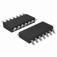
IC OSCILLATOR TIMER PROG 14SOIC

MC14541BDR2

Manufacturer Part Number
MC14541BDR2
Description
IC OSCILLATOR TIMER PROG 14SOIC
Manufacturer
ON Semiconductor
Type
Programmable Timerr
Datasheet

Specifications of MC14541BDR2

Frequency
3MHz
Voltage - Supply
3 V ~ 18 V
Current - Supply
15µA
Operating Temperature
-55°C ~ 125°C
Package / Case
14-SOIC (3.9mm Width), 14-SOL
# Internal Timers
1
Quiescent Current
20uA
Power Dissipation
500mW
Propagation Delay Time
18000ns
Operating Supply Voltage (min)
3V
Operating Supply Voltage (typ)
3.3/5/9/12/15V
Operating Supply Voltage (max)
18V
Package Type
SOIC
High Level Output Current
-16.3mA
Low Level Output Current
19.3mA
Pin Count
14
Operating Temp Range
-55C to 125C
Operating Temperature Classification
Military
Mounting
Surface Mount
Lead Free Status / RoHS Status
Contains lead / RoHS non-compliant
Count
-
Lead Free Status / Rohs Status
Not Compliant
Other names
MC14541BDR2OSCT

Available stocks

Company
Part Number
Manufacturer
Quantity
Price
Part Number:
MC14541BDR2
Manufacturer:
MOT
Quantity:
20 000
Part Number:
MC14541BDR2G
Manufacturer:
ON Semiconductor
Quantity:
7 400
Part Number:
MC14541BDR2G
Manufacturer:
ON/安森美
Quantity:
20 000
Part Number:
MC14541BDR2G
Manufacturer:
ON
Quantity:
18 695
Company:
Part Number:
MC14541BDR2G
Quantity:
4 500
Company:
Part Number:
MC14541BDR2G
Quantity:
4 500
Company:
Part Number:
MC14541BDR2G
Quantity:
29
MC14541B
Programmable Timer
counter, an integrated oscillator for use with an external capacitor and
two resistors, an automatic power−on reset circuit, and output control
logic.
reset is enabled and initializes the counter, within the specified V
range. With the power already on, an external reset pulse can be
applied. Upon release of the initial reset command, the oscillator will
oscillate with a frequency determined by the external RC network. The
16−stage counter divides the oscillator frequency (f
stage frequency being f
Features
© Semiconductor Components Industries, LLC, 2006
October, 2006 − Rev. 10
The MC14541B programmable timer consists of a 16−stage binary
Timing is initialized by turning on power, whereupon the power−on
range and ± 20% supply and ± 3% over processing at < 10 kHz)
(Apply external clock to Pin 3)
Operation
Provide No Active Power Dissipation
Rise and Fall Times
Supply Voltage Range =
Supply Voltage Range
Supply Voltage Range =
Available Outputs 2
Increments on Positive Edge Clock Transitions
Built−in Low Power RC Oscillator (± 2% accuracy over temperature
Oscillator May Be Bypassed if External Clock Is Available
External Master Reset Totally Independent of Automatic Reset
Operates as 2
Q/Q Select Provides Output Logic Level Flexibility
Reset (auto or master) Disables Oscillator During Resetting to
Clock Conditioning Circuit Permits Operation with Very Slow Clock
Automatic Reset Initializes All Counters On Power Up
Supply Voltage Range = 3.0 Vdc to 18 Vdc with Auto Reset
Pb−Free Packages are Available
n
Frequency Divider or Single Transition Timer
8
V
MR
osc
NC
, 2
R
C
AR
R
SS
PIN ASSIGNMENT
tc
tc
S
NC = NO CONNECTION
= 8.5 Vdc to 18 Vdc with Auto Reset
/2
10
Disabled (Pin 5 = V
Enabled (Pin 5 = V
n
, 2
1
2
3
4
5
6
7
.
13
or 2
16
14
13
12
11
10
9
8
V
B
A
NC
MODE
Q/Q SEL
Q
DD
SS
DD
)
)
osc
) with the n
1
DD
th
See detailed ordering and shipping information in the package
dimensions section on page 2 of this data sheet.
(Note: Microdot may be in either location)
ORDERING INFORMATION
A
WL, L
YY, Y
WW, W
G or G
http://onsemi.com
CASE 751A
CASE 948G
SOEIAJ−14
DT SUFFIX
TSSOP−14
CASE 646
CASE 965
D SUFFIX
P SUFFIX
F SUFFIX
SOIC−14
PDIP−14
= Assembly Location
= Wafer Lot
= Year
= Work Week
= Pb−Free Package
Publication Order Number:
14
1
14
14
1
1
DIAGRAMS
MC14541BCP
MARKING
AWLYYWWG
14
1
MC14541B
MC14541B/D
AWLYWW
ALYWG
14541BG
ALYWG
541B
14
G

Related parts for MC14541BDR2

MC14541BDR2 Summary of contents

Page 1

MC14541B Programmable Timer The MC14541B programmable timer consists of a 16−stage binary counter, an integrated oscillator for use with an external capacitor and two resistors, an automatic power−on reset circuit, and output control logic. Timing is initialized by turning on ...

Page 2

... Plastic “P and D/DW” Packages: – 7.0 mW/_C From 65_C To 125_C ORDERING INFORMATION Device MC14541BCP MC14541BCPG MC14541BD MC14541BDG MC14541BDR2 MC14541BDR2G MC14541BDTR2 MC14541BDTR2G MC14541BF MC14541BFG MC14541BFEL MC14541BFELG †For information on tape and reel specifications, including part orientation and tape sizes, please refer to our Tape and Reel Packaging Specifications Brochure, BRD8011/D. *This package is inherently Pb− ...

Page 3

ELECTRICAL CHARACTERISTICS Î Î Î Î Î ...

Page 4

SWITCHING CHARACTERISTICS (Note 5) Î Î Î ...

Page 5

8−STAGE OSC C tc COUNTER R 3 RESET S RESET AUTO RESET POWER−ON 5 RESET 6 MASTER RESET V = PIN PIN 7 SS FREQUENCY ...

Page 6

TYPICAL RC OSCILLATOR CHARACTERISTICS 8 −4.0 −8.0 5.0 V − kW 10.15 kHz @ 120 kW 7.8 kHz @ V ...

Page 7

−T− SEATING PLANE 0.13 (0.005) PACKAGE DIMENSIONS PDIP−14 CASE 646−06 ISSUE http://onsemi.com 7 NOTES: 1. DIMENSIONING AND TOLERANCING PER ANSI ...

Page 8

... G −T− SEATING 14 PL PLANE 0.25 (0.010 14X 0.58 *For additional information on our Pb−Free strategy and soldering details, please download the ON Semiconductor Soldering and Mounting Techniques Reference Manual, SOLDERRM/D. SOIC−14 CASE 751A−03 ISSUE 0.25 (0.010 ...

Page 9

... S A −V− C 0.10 (0.004) −T− SEATING G D PLANE 14X 0.36 *For additional information on our Pb−Free strategy and soldering details, please download the ON Semiconductor Soldering and Mounting Techniques Reference Manual, SOLDERRM/D. PACKAGE DIMENSIONS TSSOP−14 CASE 948G−01 ISSUE 0.25 (0.010) ...

Page 10

... Opportunity/Affirmative Action Employer. This literature is subject to all applicable copyright laws and is not for resale in any manner. PUBLICATION ORDERING INFORMATION LITERATURE FULFILLMENT: Literature Distribution Center for ON Semiconductor P.O. Box 5163, Denver, Colorado 80217 USA Phone: 303−675−2175 or 800−344−3860 Toll Free USA/Canada Fax: 303− ...

Related keywords