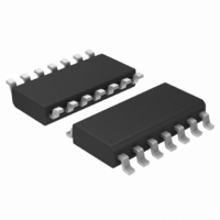
MC14541BDR2 ON Semiconductor, MC14541BDR2 Datasheet - Page 6

MC14541BDR2
Manufacturer Part Number
MC14541BDR2
Description
IC OSCILLATOR TIMER PROG 14SOIC
Manufacturer
ON Semiconductor
Type
Programmable Timerr
Datasheet
1.MC14541BDR2.pdf
(10 pages)
Specifications of MC14541BDR2
Frequency
3MHz
Voltage - Supply
3 V ~ 18 V
Current - Supply
15µA
Operating Temperature
-55°C ~ 125°C
Package / Case
14-SOIC (3.9mm Width), 14-SOL
# Internal Timers
1
Quiescent Current
20uA
Power Dissipation
500mW
Propagation Delay Time
18000ns
Operating Supply Voltage (min)
3V
Operating Supply Voltage (typ)
3.3/5/9/12/15V
Operating Supply Voltage (max)
18V
Package Type
SOIC
High Level Output Current
-16.3mA
Low Level Output Current
19.3mA
Pin Count
14
Operating Temp Range
-55C to 125C
Operating Temperature Classification
Military
Mounting
Surface Mount
Lead Free Status / RoHS Status
Contains lead / RoHS non-compliant
Count
-
Lead Free Status / Rohs Status
Not Compliant
Other names
MC14541BDR2OSCT
Available stocks
Company
Part Number
Manufacturer
Quantity
Price
Part Number:
MC14541BDR2
Manufacturer:
MOT
Quantity:
20 000
Company:
Part Number:
MC14541BDR2G
Manufacturer:
ON Semiconductor
Quantity:
7 400
Part Number:
MC14541BDR2G
Manufacturer:
ON/安森美
Quantity:
20 000
initialized by turning on power. Or with power already on,
the counter circuit is reset when the Master Reset pin is set
to a “1”. Both types of reset will result in synchronously
resetting all counter stages independent of counter state.
Auto Reset pin when set to a “1” provides a low power
operation.
a frequency determined by the external RC network i.e.,
and R
to output any one of four counter stages (2
2
Table represents the Q output of the N
When A is “1”, 2
16
t
With Auto Reset pin set to a “0” the counter circuit is
The RC oscillator as shown in Figure 3 will oscillate with
The time select inputs (A and B) provide a two−bit address
MR
−4.0
−8.0
−12
−16
). The 2
8.0
4.0
0
−55
INPUT
f =
R
C = 1000 pF
S
TC
≈ 2 R
2.3 R
= 56 kW,
n
−25
counts as shown in the Frequency Selection
NC
1
tc
R
Figure 4. RC Oscillator Stability
tc
16
tc
C
C
R
tc
is selected for both states of B. However,
tc
T
S
AR
MR
A
, AMBIENT TEMPERATURE (°C)
0
R
R
S
S
where R
= 0, f = 10.15 kHz @ V
= 120 kW, f = 7.8 kHz @ V
if (1 kHz v f v 100 kHz)
1
2
3
4
5
6
7
25
TYPICAL RC OSCILLATOR CHARACTERISTICS
S
10 V
5.0 V
50
≥ 10 kW
V
th
DD
stage of the counter.
14
13
12
10
11
= 15 V
DD
9
8
= 10 V, T
OPERATING CHARACTERISTICS
DD
75
MODE
8
DIGITAL TIMER APPLICATION
= 10 V, T
Q/Q
, 2
t + t
10
A
MR
= 25°C
, 2
100
A
= 25°C
OUTPUT
http://onsemi.com
13
V
B
A
N.C.
V
DD
DD
and
125
6
when B is “0”, normal counting is interrupted and the 9th
counter stage receives its clock directly from the oscillator
(i.e., effectively outputting 2
output level. When the counter is in a reset condition and
Q/Q select pin is set to a “0” the Q output is a “0”,
correspondingly when Q/Q select pin is set to a “1” the Q
output is a “1”.
count is continually transmitted to the output. But, with
mode pin “0” and after a reset condition the R
Expanded Block Diagram) resets, counting commences,
and after 2
output to change state. Hence, after another 2
output will not change. Thus, a Master Reset pulse must be
applied or a change in the mode pin level is required to reset
the single cycle operation.
internal counters and latch are reset. The Q output goes high
and remains high until the selected (via A and B) number of
clock pulses are counted, the Q output then goes low and
remains low until another input pulse is received.
input frequency. An external clock can be used (pin 3 is the
clock input, pins 1 and 2 are outputs) if additional accuracy
is needed.
output is required immediately following initial power up,
during which time Q output will be high.
100
5.0
2.0
1.0
0.5
0.2
0.1
50
20
10
The Q/Q select output control pin provides for a choice of
When the mode control pin is set to a “1”, the selected
When Master Reset (MR) receives a positive pulse, the
This “one shot” is fully retriggerable and as accurate as the
Notice that a setup time equal to the desired pulse width
0.0001
1.0 k
f AS A FUNCTION
(R
(R
TC
S
Figure 5. RC Oscillator Frequency as a
n−1
= 120 kW)
OF C
= 56 kW)
counts the R
Function of R
R
0.001
10 k
TC
C, CAPACITANCE (mF)
, RESISTANCE (OHMS)
S
flip−flop sets which causes the
8
).
tc
and C
100 k
0.01
f AS A FUNCTION
V
(C = 1000 pF)
tc
(R
DD
OF R
S
S
= 10 V
≈ 2R
n−1
flip−flop (see
TC
TC
counts the
)
1.0 m
0.1


