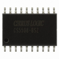
CS5508-BSZ Cirrus Logic Inc, CS5508-BSZ Datasheet - Page 20

CS5508-BSZ
Manufacturer Part Number
CS5508-BSZ
Description
IC ADC 20BIT LOW PWR 20-SOIC
Manufacturer
Cirrus Logic Inc
Datasheet
1.CS5507-ASZ.pdf
(40 pages)
Specifications of CS5508-BSZ
Data Interface
Serial
Number Of Bits
20
Sampling Rate (per Second)
100
Number Of Converters
1
Power Dissipation (max)
4.5mW
Voltage Supply Source
Analog and Digital, Dual ±
Operating Temperature
-40°C ~ 85°C
Mounting Type
Surface Mount
Package / Case
20-SOIC
Resolution (bits)
20bit
Sampling Rate
100SPS
Input Channel Type
Differential
Supply Current
340µA
Digital Ic Case Style
SOIC
No. Of Pins
20
Lead Free Status / RoHS Status
Lead free / RoHS Compliant
Other names
598-1099-5
Available stocks
Company
Part Number
Manufacturer
Quantity
Price
Part Number:
CS5508-BSZ
Manufacturer:
CIRRUS
Quantity:
20 000
20
If the CS5505/6/7/8 is operated at a clock rate
other than 32.768 kHz, the filter characteristics,
including the comb filter zeros, will scale with
the operating clock frequency. Therefore, opti-
mum rejection of line frequency interference will
occur with the CS5505/6/7/8 running at
32.768 kHz. The CS5505/6/7/8 can be used with
external clock rates from 30 kHz to 163 kHz.
Anti-Alias Considerations for Spectral
Measurement Applications
Input frequencies greater than one half the out-
put word rate (CONV = 1) may be aliased by
the converter. To prevent this, input signals
should be limited in frequency to no greater than
one half the output word rate of the converter
(when CONV =1). Frequencies close to the
modulator sample rate (XIN/2) and multiples
thereof may also be aliased. If the signal source
includes spectral components above one half the
output word rate (when CONV = 1) these com-
20
CONV
CAL
A0
A1
XOUT
22.5 pF
gm ~ ~ 19 umho
Figure 12. Gate Oscillator and Control Logic
D Q
CLK
D Q
CLK
10 MΩ
R
XTL=32.768 kHz
15 pF
Decoder
Input
CS5505/6
Mux
XIN
S Q
R
S Q
R
T
Q
Channel A0 A1
ponents should be removed by means of low-
pass filtering prior to the A/D input to prevent
aliasing. Spectral components greater than one
half the output word rate on the VREF inputs
(VREF+ and VREF-) may also be aliased. Fil-
tering of the reference voltage to remove these
spectral components from the reference voltage
is desirable.
Crystal Oscillator
The CS5505/6/7/8 is designed to be operated us-
ing a 32.768 kHz "tuning fork" type crystal. One
end of the crystal should be connected to the
XIN input. The other end should be attached to
XOUT. Short lead lengths should be used to
minimize stray capacitance. Figure 12 illustrates
the gate oscillator, and a simplified version of
the control logic used on the chip.
Over the industrial temperature range (-40 to
+85 °C) the on-chip gate oscillator will oscillate
1
2
3
4
D Q
CLK
D Q
CLK
0
0
1
1
Start
Conversion
Start
Calibration
Modulator
Sample
Clock
0
1
0
1
CS5505/6/7/8
CS5505/6/7/8
DS59F7
DS59F4


