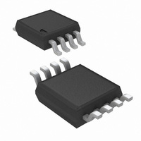
ADC121C021CIMM/NOPB National Semiconductor, ADC121C021CIMM/NOPB Datasheet - Page 18

ADC121C021CIMM/NOPB
Manufacturer Part Number
ADC121C021CIMM/NOPB
Description
IC ADC 12BIT I2C ALERT 8-MSOP
Manufacturer
National Semiconductor
Series
PowerWise®r
Datasheet
1.ADC121C021CIMMNOPB.pdf
(30 pages)
Specifications of ADC121C021CIMM/NOPB
Number Of Bits
12
Sampling Rate (per Second)
188.9k
Data Interface
I²C, Serial
Number Of Converters
1
Power Dissipation (max)
780µW
Voltage Supply Source
Single Supply
Operating Temperature
-40°C ~ 105°C
Mounting Type
Surface Mount
Package / Case
8-TSSOP, 8-MSOP (0.118", 3.00mm Width)
Number Of Elements
1
Resolution
12Bit
Architecture
SAR
Sample Rate
188.9KSPS
Input Polarity
Unipolar
Input Type
Voltage
Rated Input Volt
5.5V
Differential Input
No
Power Supply Requirement
Single
Single Supply Voltage (typ)
3.3/5V
Single Supply Voltage (min)
2.7V
Single Supply Voltage (max)
5.5V
Dual Supply Voltage (typ)
Not RequiredV
Dual Supply Voltage (min)
Not RequiredV
Dual Supply Voltage (max)
Not RequiredV
Differential Linearity Error
-0.9LSB/1LSB
Integral Nonlinearity Error
±1LSB
Operating Temp Range
-40C to 105C
Operating Temperature Classification
Industrial
Mounting
Surface Mount
Pin Count
8
Package Type
MSOP
Input Signal Type
Single-Ended
Lead Free Status / RoHS Status
Lead free / RoHS Compliant
Other names
ADC121C021CIMMTR
www.national.com
1.6.4 Configuration Register
Pointer Address 02h (Read/Write)
Default Value: 00h
1.6.5 V
This register holds the lower limit threshold used to determine the alert condition. If the conversion moves lower than this limit, a
V
Pointer Address 03h (Read/Write)
Default Value: 0000h
Cycle Time [2:0]
Bits
7:5
4
3
2
1
0
Bits
15:12
11:0
D7
Cycle Time[2:0]
D7
(See Table at
LOW
0
D15
right)
alert is generated.
D7
D6
LOW
D6
0
Name
Cycle Time
Alert Hold
Alert Flag Enable
Alert Pin Enable
Reserved
Polarity
Name
Reserved
V
LOW
-- Alert Limit Register - Under Range
D5
D5
0
Limit
Alert
Hold
D4
Automatic Mode Disabled
D14
D6
Enable
Reserved
Alert
Flag
Conversion
D3
Interval
Description
Configures Automatic Conversion mode. When these bits are set to zeros, the automatic
conversion mode is disabled. This is the case at power-up.
When these bits are set to a non-zero value, the ADC will begin operating in automatic conversion
mode. (See Section
different values provide various conversion intervals.
0: Alerts will self-clear when the measured voltage moves within the limits by more than the
hysteresis register value.
1: Alerts will not self-clear and are only cleared when a one is written to the alert high flag or the
alert low flag in the Alert Status register.
0: Disables alert status bit [D15] in the Conversion Result register.
1: Enables alert status bit [D15] in the Conversion Result register.
0: Disables the ALERT output pin. The ALERT output will be high impedance when the pin is
disabled.
1: Enables the ALERT output pin.
*This bit does not apply to and is a "don't care" for the ADC121C027.
Always reads zeros. Zeros must be written to this bit.
This bit configures the active level polarity of the ALERT output pin.
0: Sets the ALERT pin to active low.
1: Sets the ALERT pin to active high.
*This bit does not apply to and is a "don't care" for the ADC121C027.
Description
Always reads zeros. Zeros must be written to these bits.
Lower limit threshold. D11 is MSB.
Enable
Alert
Pin
D13
D2
D5
D1
0
Typical
f
(ksps)
convert
Polarity
1.9 AUTOMATIC CONVERSION
D12
0
D4
D0
V
LOW
Limit [7:0]
18
0
0
0
1
1
1
1
D11
D3
0
1
1
0
0
1
1
1
0
1
0
1
0
1
D10
MODE). The Cycle Time table shows how
D2
V
LOW
Limit [11:8]
T
T
T
T
T
T
T
convert
convert
convert
convert
convert
convert
convert
x 1024
x 2048
x 128
x 256
x 512
D9
D1
x 32
x 64
D8
D0
13.5
6.7
3.4
1.7
0.9
0.4
27


