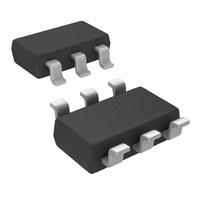
ADC121C021CIMK/NOPB National Semiconductor, ADC121C021CIMK/NOPB Datasheet - Page 17

ADC121C021CIMK/NOPB
Manufacturer Part Number
ADC121C021CIMK/NOPB
Description
IC ADC 12BIT I2C ALERT TSOT23-6
Manufacturer
National Semiconductor
Series
PowerWise®r
Datasheet
1.ADC121C021CIMMNOPB.pdf
(30 pages)
Specifications of ADC121C021CIMK/NOPB
Number Of Bits
12
Sampling Rate (per Second)
188.9k
Data Interface
I²C, Serial
Number Of Converters
1
Power Dissipation (max)
780µW
Voltage Supply Source
Single Supply
Operating Temperature
-40°C ~ 105°C
Mounting Type
Surface Mount
Package / Case
SOT-23-6 Thin, TSOT-23-6
Lead Free Status / RoHS Status
Lead free / RoHS Compliant
Other names
ADC121C021CIMK
ADC121C021CIMK
ADC121C021CIMKTR
ADC121C021CIMK
ADC121C021CIMKTR
1.6.2 Conversion Result Register
This register holds the result of the most recent conversion. In the normal mode, a new conversion is started whenever this register
is read. The conversion result data is in straight binary format with the MSB at D11.
Pointer Address 00h (Read Only)
Default Value: 0000h
1.6.3 Alert Status Register
This register indicates if a high or a low threshold has been violated. The bits of this register are active high. That is, a high indicates
that the respective limit has been violated.
Pointer Address 01h (Read/Write)
Default Value: 00h
Bits
15
14:12
11:0
Bits
7:2
1
0
Alert Flag
D15
D7
D7
Name
Alert Flag
Reserved
Conversion Result
Name
Reserved
Over Range
Alert Flag
Under Range
Alert Flag
D14
D6
D6
Description
This bit indicates when an alert condition has occurred. When the Alert Bit Enable is set in the
Configuration Register, this bit will be high if either alert flag is set in the Alert Status Register.
Otherwise, this bit is a zero. The I
other data registers to determine the source of the alert.
Always reads zeros.
The Analog-to-Digital conversion result. The Conversion result data is a 12-bit data word in
straight binary format. The MSB is D11.
Description
Always reads zeros. Zeros must be written to these bits.
Bit is set to 1 when the measured voltage exceeds the V
V
controller writes a one to this bit. (2) The measured voltage decreases below the programmed
V
Alert Hold bit is cleared in the Configuration register. If the Alert Hold bit is set, the only way to
clear an over range alert is to write a zero to this bit.
Bit is set to 1 when the measured voltage falls below the V
V
controller writes a one to this bit. (2) The measured voltage increases above the programmed
V
cleared in the Configuration register. If the Alert Hold bit is set, the only way to clear an under
range alert is to write a zero to this bit.
HIGH
HIGH
LOW
LOW
Reserved
D13
D5
D5
limit register. Flag is reset to 0 when one of the following two conditions is met: (1) The
limit plus the programmed V
limit minus the programmed V
limit register. Flag is reset to 0 when one of the following two conditions is met: (1) The
Reserved
Conversion Result [7:0]
D12
D4
D4
17
2
HYST
C controller will typically read the Alert Status register and
HYST
D11
D3
D3
value. The alert will only self-clear if the Alert Hold bit is
value (See
Conversion Result [11:8]
Figure
D10
D2
D2
HIGH
LOW
9) . The alert will only self-clear if the
limit stored in the programmable
limit stored in the programmable
Over Range
Alert
D9
D1
D1
Under Range
www.national.com
Alert
D8
D0
D0


