AD7450ARMZ Analog Devices Inc, AD7450ARMZ Datasheet
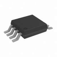
IC ADC 12BIT DIFF IN 1MSPS 8MSOP

AD7450ARMZ

Manufacturer Part Number
AD7450ARMZ
Description
IC ADC 12BIT DIFF IN 1MSPS 8MSOP
Manufacturer
Analog Devices Inc
Datasheet

Specifications of AD7450ARMZ

Data Interface
DSP, MICROWIRE™, QSPI™, Serial, SPI™
Number Of Bits
12
Sampling Rate (per Second)
1M
Number Of Converters
1
Power Dissipation (max)
9.25mW
Voltage Supply Source
Single Supply
Operating Temperature
-40°C ~ 85°C
Mounting Type
Surface Mount
Package / Case
8-TSSOP, 8-MSOP (0.118", 3.00mm Width)
Resolution (bits)
12bit
Input Channel Type
Differential
Supply Voltage Range - Analogue
2.7V To 3.3V, 4.75V To 5.25V
Supply Current
1.8mA
No. Of Pins
8
Operating
RoHS Compliant
Sampling Rate
1MSPS
Rohs Compliant
Yes
Lead Free Status / RoHS Status
Lead free / RoHS Compliant
For Use With
EVAL-AD7450CBZ - BOARD EVALUATION FOR AD7450
Lead Free Status / RoHS Status
Lead free / RoHS Compliant

Available stocks

Company
Part Number
Manufacturer
Quantity
Price
Part Number:
AD7450ARMZ
Manufacturer:
ADI/亚德诺
Quantity:
20 000
a
GENERAL DESCRIPTION
The AD7450 is a 12-bit, high-speed, low power, successive
approximation (SAR) analog-to-digital converter that features a
fully differential analog input. It operates from a single 3 V or 5 V
power supply and features throughput rates up to 833 kSPS or
1 MSPS, respectively.
This part contains a low noise, wide bandwidth, differential track-
and-hold amplifier (T/H) that can handle input frequencies in
excess of 1 MHz with the –3 dB point typically being 20 MHz.
The reference voltage for the AD7450 is applied externally to the
V
on the power supply and what suits the application. The value of
the reference voltage determines the common-mode voltage
range of the part. With this truly differential input structure and
variable reference input, the user can select a variety of input
ranges and bias points.
The conversion and data acquisition processes are controlled
using CS and the serial clock, allowing the device to interface
with microprocessors or DSPs. The input signals are sampled
on the falling edge of CS, and the conversion is also initiated at
this point.
The SAR architecture of this part ensures that there are no
pipeline delays.
SPI and QSPI are trademarks of Motorola, Inc.
MICROWIRE is a trademark of National Semiconductor Corporation.
REV. 0
Information furnished by Analog Devices is believed to be accurate and
reliable. However, no responsibility is assumed by Analog Devices for its
use, nor for any infringements of patents or other rights of third parties that
may result from its use. No license is granted by implication or otherwise
under any patent or patent rights of Analog Devices.
REF
FEATURES
Fast Throughput Rate: 1 MSPS
Specified for V
Low Power at Max Throughput Rate:
Fully Differential Analog Input
Wide Input Bandwidth:
Flexible Power/Serial Clock Speed Management
No Pipeline Delays
High-Speed Serial Interface—SPI
Power-Down Mode: 1 A Max
8-Lead SOIC and SOIC Packages
APPLICATIONS
Transducer Interface
Battery-Powered Systems
Data Acquisition Systems
Portable Instrumentation
Motor Control
Communications
3.75 mW Max at 833 kSPS with 3 V Supplies
9 mW Max at 1 MSPS with 5 V Supplies
70 dB SINAD at 300 kHz Input Frequency
MICROWIRE
pin and can be varied from 100 mV to 3.5 V, depending
TM
DD
/DSP Compatible
of 3 V and 5 V
TM
/QSPI
TM
12-Bit ADC in SOIC-8 and SO-8
The AD7450 uses advanced design techniques to achieve low
power dissipation at high throughput rates.
PRODUCT HIGHLIGHTS
1. Operation with either 3 V or 5 V power supplies.
2. High throughput with low power consumption. With a 3 V
3. Fully differential analog input.
4. Flexible power/serial clock speed management. The conversion
5. Variable voltage reference input.
6. No pipeline delay.
7. Accurate control of the sampling instant via a CS input and
8. ENOB > 8 bits typically with 100 mV reference.
One Technology Way, P.O. Box 9106, Norwood, MA 02062-9106, U.S.A.
Tel: 781/329-4700
Fax: 781/326-8703
supply, the AD7450 offers 3.75 mW max power consumption
for 833 kSPS throughput.
rate is determined by the serial clock, allowing the power
to be reduced as the conversion time is reduced through
the serial clock speed increase. This part also features a
shutdown mode to maximize power efficiency at lower
throughput rates.
once-off conversion control.
V
V
V
REF
IN+
IN–
Differential Input, 1 MSPS
FUNCTIONAL BLOCK DIAGRAM
GND
AD7450
V
DD
T/H
12-BIT SUCCESSIVE
APPROXIMATION
CONTROL
LOGIC
ADC
© Analog Devices, Inc., 2002
AD7450
www.analog.com
SCLK
SDATA
CS

Related parts for AD7450ARMZ

AD7450ARMZ Summary of contents

Page 1

FEATURES Fast Throughput Rate: 1 MSPS Specified for and Low Power at Max Throughput Rate: 3.75 mW Max at 833 kSPS with 3 V Supplies 9 mW Max at 1 MSPS with ...

Page 2

AD7450–SPECIFICATIONS MHz SCLK S Parameter DYNAMIC PERFORMANCE Signal-to-(Noise + Distortion) Ratio 3 (SINAD) 3 Total Harmonic Distortion (THD) 3 Peak Harmonic or Spurious Noise 3 Intermodulation Distortion (IMD) ...

Page 3

Parameter Conditions/Comments CONVERSION RATE Conversion Time 888 ns with an 18 MHz SCLK 1.07 µs with a 15 MHz SCLK Track-and-Hold Sine Wave Input 3, 8 Acquisition Time 9 Throughput Rate V V POWER REQUIREMENTS Range ± 10%; ...

Page 4

AD7450 1, 2 TIMING SPECIFICATIONS MHz MSPS 2 SCLK S REF Limit MIN MAX Parameter SCLK 15 18 ...

Page 5

ABSOLUTE MAXIMUM RATINGS (T = 25°C, unless otherwise noted GND . . . . . . . . . . . . . . . . . . . . . . . . . . ...

Page 6

AD7450 Pin Number Mnemonic 1 V REF IN– 4 GND SDATA 7 SCLK PIN CONFIGURATION REF AD7450 V SCLK 2 7 IN+ TOP VIEW ...

Page 7

TERMINOLOGY Signal-to-(Noise + Distortion) Ratio This is the measured ratio of signal-to-(noise + distortion) at the output of the ADC. The signal is the rms amplitude of the fundamental. Noise is the sum of all nonfundamental signals up to half ...

Page 8

AD7450–Typical Performance Characteristics (Default Conditions 8192 POINT FFT f = 1MSPS SAMPLE – 300kHz IN SINAD = 71.7dB THD = –82.8dB –40 PK NOISE = –85.3dB –60 –80 –100 –120 0 50 ...

Page 9

POSITIVE INL 0.5 0 –0.5 NEGATIVE INL –1.0 –1.5 0 0.5 1.0 1.5 2.0 2.5 3.0 3.5 V REF TPC 10. Change in INL vs. Reference Voltage 10,000 10,000 9,000 CODES 8,000 V ...

Page 10

AD7450 CIRCUIT INFORMATION The AD7450 is a fast, low power, single-supply, 12-bit successive approximation analog-to-digital converter (ADC). It can operate with and 3 V power supply and is capable of throughput rates MSPS and ...

Page 11

p-p CM* V REF IN+ AD7450 SDATA V p-p CM* V REF IN– V REF 1.25V/2.5V V REF 0.1 F *CM = COMMON-MODE VOLTAGE Figure 6. Typical Connection Diagram THE ANALOG INPUT The ...

Page 12

AD7450 REFERENCE = 1.25V V IN COMMON-MODE (CM 0.625V MIN CM = 4.42V V MAX IN REFERENCE = 2. COMMON-MODE (CM 1.25V MIN CM = 3.75V MAX V IN Figure 10. Examples of the ...

Page 13

GND –2.5V *MOUNT AS CLOSE TO THE AD7450 AS POSSIBLE AND ENSURE HIGH PRECISION Rs AND Cs ARE USED Rs – 50R; C – 1nF; Rg1 = Rf1 = Rf2 = 499R; Rg2 = 523R Figure 14. Using the ...

Page 14

AD7450 The circuit configuration shown in Figure 15b converts a unipolar, single-ended signal into a differential signal. 220 2 V p-p REF V+ 390 VREF GND V– 220 220 V+ A V– 10k Figure 15b. Dual Op Amp Circuit to ...

Page 15

SINGLE-ENDED OPERATION When supplied with power supply, the AD7450 can handle a single-ended input. The design of this part is optimized for differential operation, so with a single-ended input, performance will degrade. Linearity will typically degrade by ...

Page 16

AD7450 SCLK SDATA LEADING ZEROS 10ns SCLK 1 2 MODES OF OPERATION The mode of operation of the AD7450 is selected by controlling the logic state ...

Page 17

SCLK SDATA Figure 22. Entering Power-Down Mode Once CS has been brought high in this window of SCLKs, the part will enter power-down, the conversion that was initiated by the falling edge of CS will be terminated, ...

Page 18

AD7450 POWER VERSUS THROUGHPUT RATE By using the power-down mode on the AD7450 when not converting, the average power consumption of the ADC decreases at lower throughput rates. Figure 24 shows how, as the throughput rate is reduced, the device ...

Page 19

AD7450 to TMS320C5x/C54x The serial interface on the TMS320C5x/C54x uses a continuous serial clock and frame synchronization signals to synchronize the data transfer operations with peripheral devices, such as the AD7450. The CS input allows easy interfacing between the TMS320C5x/C54x ...

Page 20

AD7450 EVALUATING THE AD7450 PERFORMANCE The evaluation board package includes a fully assembled and tested evaluation board, documentation, and software for controlling the board from a PC via the Evaluation Board Controller. The Evaluation Board Controller can be used in ...

Related keywords