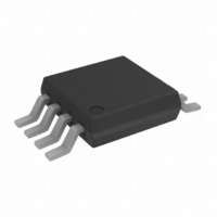
AD7450ARMZ Analog Devices Inc, AD7450ARMZ Datasheet - Page 3

AD7450ARMZ
Manufacturer Part Number
AD7450ARMZ
Description
IC ADC 12BIT DIFF IN 1MSPS 8MSOP
Manufacturer
Analog Devices Inc
Datasheet
1.AD7450ARMZ.pdf
(20 pages)
Specifications of AD7450ARMZ
Data Interface
DSP, MICROWIRE™, QSPI™, Serial, SPI™
Number Of Bits
12
Sampling Rate (per Second)
1M
Number Of Converters
1
Power Dissipation (max)
9.25mW
Voltage Supply Source
Single Supply
Operating Temperature
-40°C ~ 85°C
Mounting Type
Surface Mount
Package / Case
8-TSSOP, 8-MSOP (0.118", 3.00mm Width)
Resolution (bits)
12bit
Input Channel Type
Differential
Supply Voltage Range - Analogue
2.7V To 3.3V, 4.75V To 5.25V
Supply Current
1.8mA
No. Of Pins
8
Operating
RoHS Compliant
Sampling Rate
1MSPS
Rohs Compliant
Yes
Lead Free Status / RoHS Status
Lead free / RoHS Compliant
For Use With
EVAL-AD7450CBZ - BOARD EVALUATION FOR AD7450
Lead Free Status / RoHS Status
Lead free / RoHS Compliant
Available stocks
Company
Part Number
Manufacturer
Quantity
Price
Part Number:
AD7450ARMZ
Manufacturer:
ADI/亚德诺
Quantity:
20 000
Parameter
CONVERSION RATE
POWER REQUIREMENTS
NOTES
1
2
3
4
5
6
7
8
9
10
11
REV. 0
Temperature range is as follows: A and B Versions: –40°C to +85°C.
Common-mode voltage. The input signal can be centered on any choice of dc common-mode voltage as long as this value is in the range specified in Figures 8 and 9.
See Terminology section.
A 200 mV p-p sine wave, varying in frequency from 1 kHz to 200 kHz is coupled onto V
If the input spans of V
The AD7450 is functional with a reference input from 100 mV and for V
The AD7450 is functional with a reference input from 100 mV and for V
Sample tested @ 25°C to ensure compliance.
See Serial Interface section.
See Power Versus Throughput Rate section.
Measured with a midscale dc input.
Conversion Time
Track-and-Hold
Acquisition Time
Throughput Rate
V
I
Power Dissipation
Full Power-Down Mode
DD
DD
Normal Mode (Static)
Normal Mode (Operational)
Full Power-Down Mode
Normal Mode (Operational)
10, 11
IN+
3, 8
9
and V
IN–
are both V
REF
Conditions/Comments
888 ns with an 18 MHz SCLK
1.07 µs with a 15 MHz SCLK
Sine Wave Input
V
V
Range: 3 V ± 10%; 5 V ± 5%
V
V
V
SCLK ON or OFF
V
1.38 mW typ for 100 KSPS
V
0.53 mW typ for 100 KSPS
V
V
, and they are 180° out of phase, the differential voltage is 2
DD
DD
DD
DD
DD
DD
DD
DD
DD
= 5 V; f
= 3 V; f
= 5 V
= 3 V
= 3 V/5 V SCLK; ON or OFF
= 5 V; f
= 3 V; f
= 5 V; SCLK ON or OFF
= 3 V; SCLK ON or OFF
SAMPLE
SAMPLE
SAMPLE
SAMPLE
= 1 MSPS
= 833 kSPS
= 1 MSPS;
= 833 kSPS;
DD
DD
= 5 V, the reference can range up to 3.5 V (see References section).
= 3 V, the reference can range up to 2.2 V (see References section).
–3–
10
10
DD
. A 2.2 nF capacitor is used to decouple V
A Version
16
200
1
833
3/5
0.5
1.8
1.25
1
9
3.75
5
3
V
REF
.
B Version
16
200
1
833
3/5
0.5
1.8
1.25
1
9
3.75
5
3
DD
to GND.
Unit
SCLK Cycles
ns max
MSPS max
kSPS max
V min/max
mA typ
mA max
mA max
µA max
mW max
mW max
µW max
µW max
AD7450


