ADC0804LCN Intersil, ADC0804LCN Datasheet - Page 9
ADC0804LCN
Manufacturer Part Number
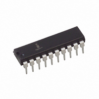
ADC0804LCN
Description
IC ADC 8-BIT 10KSPS 1LSB 20-DIP
Manufacturer
Intersil
Datasheet
1.ADC0804LCN.pdf
(17 pages)
Specifications of ADC0804LCN
Number Of Bits
8
Sampling Rate (per Second)
10k
Data Interface
Parallel
Number Of Converters
1
Voltage Supply Source
Single Supply
Operating Temperature
0°C ~ 70°C
Mounting Type
Through Hole
Package / Case
20-DIP (0.300", 7.62mm)
Lead Free Status / RoHS Status
Contains lead / RoHS non-compliant
Other names
ADC0804LCNIN
ADC0804LCNIN
ADC0804LCNIN
Available stocks
Company
Part Number
Manufacturer
Quantity
Price
Company:

Part Number:
ADC0804LCN
Manufacturer:
MICROCHIP
Quantity:
2 000
Company:
Part Number:
ADC0804LCN
Manufacturer:
NS
Quantity:
432
Company:
Part Number:
ADC0804LCN
Manufacturer:
TI
Quantity:
100
Part Number:
ADC0804LCN
Manufacturer:
NS/国半
Quantity:
20 000
Company:
Part Number:
ADC0804LCN*
Manufacturer:
S/PHI
Quantity:
19
Company:
Part Number:
ADC0804LCN/NOPB
Manufacturer:
MICRON
Quantity:
1 000


successive approximation register. A correction is made to
offset the comparison by
Analog Differential Voltage Inputs and Common-
Mode Rejection
This A/D gains considerable applications flexibility from the
analog differential voltage input. The V
be used to automatically subtract a fixed voltage value from
the input reading (tare correction). This is also useful in 4mA
- 20mA current loop conversion. In addition, common-mode
noise can be reduced by use of the differential input.
The time interval between sampling V
clock periods. The maximum error voltage due to this slight
time difference between the input voltage samples is given by:
where:
V
f
For example, with a 60Hz common-mode frequency, f
a 640kHz A/D clock, f
would allow a common-mode voltage, V
or
The allowed range of analog input voltage usually places
more severe restrictions on input common-mode voltage
levels than this.
An analog input voltage with a reduced span and a relatively
large zero offset can be easily handled by making use of the
differential input (see Reference Voltage Span Adjust).
Analog Input Current
The internal switching action causes displacement currents to
flow at the analog inputs. The voltage on the on-chip
capacitance to ground is switched through the analog
differential input voltage, resulting in proportional currents
entering the V
current transients occur at the leading edge of the internal
clocks. They rapidly decay and do not inherently cause errors
as the on-chip comparator is strobed at the end of the clock
perIod.
Input Bypass Capacitors
Bypass capacitors at the inputs will average these charges
and cause a DC current to flow through the output resistances
of the analog signal sources. This charge pumping action is
worse for continuous conversions with the V
at full scale. For a 640kHz clock frequency with the V
V
V
CM
V
V
PEAK
PEAK
PEAK
E
E
is the common-mode frequency.
is the error voltage due to sampling delay,
MAX
is the peak value of the common-mode voltage,
=
=
------------------------------------------------- -
--------------------------------------------------------- -
5
=
V
2 f
6.28 60 4.5
E MAX f
IN(+)
10
V
PEAK
CM
–
3
input and leaving the V
640
CLK
4.5
CLK
2 f
, keeping this error to
1
10
CM
/
2
3
,
LSB (see Figure 11A).
9
------------
f
CLK
4.5
1.9V
.
IN(+)
PEAK
lN(-)
IN(-)
and V
IN(+)
input (pin 7) can
, given by:
1
/
input. These
4
input voltage
lN(-)
LSB (~5mV)
ADC0803, ADC0804
CM
IN(+)
is 4
, and
1
/
2
input at 5V, this DC current is at a maximum of approximately
5 A. Therefore, bypass capacitors should not be used at
the analog inputs or the V
sources (>1k ). If input bypass capacitors are necessary for
noise filtering and high source resistance is desirable to
minimize capacitor size, the effects of the voltage drop across
this input resistance, due to the average value of the input
current, can be compensated by a full scale adjustment while
the given source resistor and input bypass capacitor are both
in place. This is possible because the average value of the
input current is a precise linear function of the differential input
voltage at a constant conversion rate.
Input Source Resistance
Large values of source resistance where an input bypass
capacitor is not used will not cause errors since the input
currents settle out prior to the comparison time. If a low-
pass filter is required in the system, use a low-value series
resistor ( 1k ) for a passive RC section or add an op amp
RC active low-pass filter. For low-source-resistance
applications ( 1k ), a 0.1 F bypass capacitor at the inputs
will minimize EMI due to the series lead inductance of a long
wire. A 100 series resistor can be used to isolate this
capacitor (both the R and C are placed outside the feedback
loop) from the output of an op amp, if used.
Stray Pickup
The leads to the analog inputs (pins 6 and 7) should be kept
as short as possible to minimize stray signal pickup (EMI).
Both EMI and undesired digital-clock coupling to these inputs
can cause system errors. The source resistance for these
inputs should, in general, be kept below 5k . Larger values of
source resistance can cause undesired signal pickup. Input
bypass capacitors, placed from the analog inputs to ground,
will eliminate this pickup but can create analog scale errors as
these capacitors will average the transient input switching
currents of the A/D (see Analog Input Current). This scale
error depends on both a large source resistance and the use
of an input bypass capacitor. This error can be compensated
by a full scale adjustment of the A/D (see Full Scale
Adjustment) with the source resistance and input bypass
capacitor in place, and the desired conversion rate.
Reference Voltage Span Adjust
For maximum application flexibility, these A/Ds have been
designed to accommodate a 5V, 2.5V or an adjusted voltage
reference. This has been achieved in the design of the IC as
shown in Figure 12.
Notice that the reference voltage for the IC is either
voltage which is applied to the V+ supply pin, or is equal to
the voltage which is externally forced at the V
allows for a pseudo-ratiometric voltage reference using, for
the V+ supply, a 5V reference voltage. Alternatively, a
voltage less than 2.5V can be applied to the V
The internal gain to the V
of 2 reduction in the reference voltage.
REF
REF
/2 input is 2 to allow this factor
/2 pin for high resistance
REF
REF
/2 pin. This
/2 input.
1
/
2
of the
Related parts for ADC0804LCN
Image
Part Number
Description
Manufacturer
Datasheet
Request
R

Part Number:
Description:
Intersil Corporation [CMOS Serial Controller Interface]
Manufacturer:
Intersil Corporation
Datasheet:
Part Number:
Description:
Manufacturer:
Intersil Corporation
Datasheet:
Part Number:
Description:
357-036-542-201 CARDEDGE 36POS DL .156 BLK LOPRO
Manufacturer:
Intersil Corporation
Datasheet:
Part Number:
Description:
1024-Word x 4-Bit LSI Static RAM
Manufacturer:
Intersil Corporation
Datasheet:
Part Number:
Description:
General Purpose NPN Transistor Arrays FN341.4
Manufacturer:
Intersil Corporation
Datasheet:
Part Number:
Description:
CMOS 16-Bit Microprocessor
Manufacturer:
Intersil Corporation
Datasheet:
Part Number:
Description:
Manufacturer:
Intersil Corporation
Datasheet:
Part Number:
Description:
Manufacturer:
Intersil Corporation
Datasheet:
Part Number:
Description:
Manufacturer:
Intersil Corporation
Datasheet:
Part Number:
Description:
Manufacturer:
Intersil Corporation
Datasheet:
Part Number:
Description:
CMOS 6-Bit Latch and Decoder Memory Interfaces
Manufacturer:
Intersil Corporation
Datasheet:
Part Number:
Description:
CA3046General Purpose NPN Transistor Arrays
Manufacturer:
Intersil Corporation
Datasheet:
Part Number:
Description:
Manufacturer:
Intersil Corporation
Datasheet:
Part Number:
Description:
TR909 DLC/FLC SLIC with Low Power Standby
Manufacturer:
Intersil Corporation
Datasheet:
Part Number:
Description:
Manufacturer:
Intersil Corporation
Datasheet: