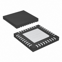
MAX1020BETX+ Maxim Integrated Products, MAX1020BETX+ Datasheet - Page 27

MAX1020BETX+
Manufacturer Part Number
MAX1020BETX+
Description
IC ADC/DAC 10BIT 36-TQFN-EP
Manufacturer
Maxim Integrated Products
Type
ADC, DACr
Datasheet
1.MAX1020BETX.pdf
(44 pages)
Specifications of MAX1020BETX+
Resolution (bits)
10 b
Sampling Rate (per Second)
225k
Data Interface
MICROWIRE™, QSPI™, Serial, SPI™
Voltage Supply Source
Analog and Digital
Voltage - Supply
4.75 V ~ 5.25 V
Operating Temperature
-40°C ~ 85°C
Mounting Type
Surface Mount
Package / Case
36-TQFN Exposed Pad
Lead Free Status / RoHS Status
Lead free / RoHS Compliant
Table 6. Unipolar-Mode Register (Addressed Through the Setup Register)
Table 7. Bipolar-Mode Register (Addressed Through the Setup Register)
BIT NAME
UCH10/11
UCH12/13
UCH14/15
BIT NAME
BCH10/11
BCH12/13
BCH14/15
UCH0/1
UCH2/3
UCH4/5
UCH6/7
UCH8/9
BCH0/1
BCH2/3
BCH4/5
BCH6/7
BCH8/9
10-Bit, Multichannel ADCs/DACs with FIFO,
7 (MSB)
0 (LSB)
7 (MSB)
______________________________________________________________________________________
0 (LSB)
BIT
BIT
6
5
4
3
2
1
6
5
4
3
2
1
Temperature Sensing, and GPIO Ports
Set to one to configure AIN0 and AIN1 for bipolar differential conversion. Set the corresponding bits
in the unipolar-mode and bipolar-mode registers to zero to configure AIN0 and AIN1 for unipolar
single-ended conversion.
Set to one to configure AIN2 and AIN3 for bipolar differential conversion. Set the corresponding bits
in the unipolar-mode and bipolar-mode registers to zero to configure AIN2 and AIN3 for unipolar
single-ended conversion.
Set to one to configure AIN4 and AIN5 for bipolar differential conversion. Set the corresponding bits
in the unipolar-mode and bipolar-mode registers to zero to configure AIN4 and AIN5 for unipolar
single-ended conversion.
Set to one to configure AIN6 and AIN7 for bipolar differential conversion. Set the corresponding bits
in the unipolar-mode and bipolar-mode registers to zero to configure AIN6 and AIN7 for unipolar
single-ended conversion.
Set to one to configure AIN8 and AIN9 for bipolar differential conversion. Set the corresponding bits
in the unipolar-mode and bipolar-mode registers to zero to configure AIN8 and AIN9 for unipolar
single-ended conversion.
Set to one to configure AIN10 and AIN11 for bipolar differential conversion. Set the corresponding
bits in the unipolar-mode and bipolar-mode registers to zero to configure AIN10 and AIN11 for
unipolar single-ended conversion.
Set to one to configure AIN12 and AIN13 for bipolar differential conversion. Set the corresponding
bits in the unipolar-mode and bipolar-mode registers to zero to configure AIN12 and AIN13 for
unipolar single-ended conversion.
Set to one to configure AIN14 and AIN15 for bipolar differential conversion. Set the corresponding
bits in the unipolar-mode and bipolar-mode registers to zero to configure AIN14 and AIN15 for
unipolar single-ended conversion.
Configure AIN0 and AIN1 for unipolar differential conversion.
Configure AIN2 and AIN3 for unipolar differential conversion.
Configure AIN4 and AIN5 for unipolar differential conversion.
Configure AIN6 and AIN7 for unipolar differential conversion.
Configure AIN8 and AIN9 for unipolar differential conversion.
Configure AIN10 and AIN11 for unipolar differential conversion.
Configure AIN12 and AIN13 for unipolar differential conversion.
Configure AIN14 and AIN15 for unipolar differential conversion.
FUNCTION
FUNCTION
27


