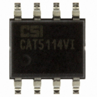
CAT5114VI-10-T3 ON Semiconductor, CAT5114VI-10-T3 Datasheet - Page 4

CAT5114VI-10-T3
Manufacturer Part Number
CAT5114VI-10-T3
Description
IC POT DIGITL 10K 32TAP 8SOIC
Manufacturer
ON Semiconductor
Datasheet
1.CAT5114ZD7I10GT3.pdf
(15 pages)
Specifications of CAT5114VI-10-T3
Taps
32
Resistance (ohms)
10K
Number Of Circuits
1
Temperature Coefficient
300 ppm/°C Typical
Memory Type
Non-Volatile
Interface
Up/Down
Voltage - Supply
2.5 V ~ 6 V
Operating Temperature
-40°C ~ 85°C
Mounting Type
Surface Mount
Package / Case
8-SOIC (3.9mm Width)
Resistance In Ohms
10K
Lead Free Status / RoHS Status
Lead free / RoHS Compliant
Other names
5114VI-10-TE13
CAT5114VI-10-T3TR
CAT5114VI-10-TE13
CAT5114VI-10-TE13TR
CAT5114VI-10-TE13TR
CAT5114VI-10-T3TR
CAT5114VI-10-TE13
CAT5114VI-10-TE13TR
CAT5114VI-10-TE13TR
Available stocks
Company
Part Number
Manufacturer
Quantity
Price
Company:
Part Number:
CAT5114VI-10-T3
Manufacturer:
NXP
Quantity:
803
Stresses exceeding Maximum Ratings may damage the device. Maximum Ratings are stress ratings only. Functional operation above the
Recommended Operating Conditions is not implied. Extended exposure to stresses above the Recommended Operating Conditions may affect
device reliability.
1. This parameter is tested initially and after a design or process change that affects the parameter.
2. Latch−up protection is provided for stresses up to 100 mA on address and data pins from −1 V to V
Table 2. OPERATION MODES
Table 3. ABSOLUTE MAXIMUM RATINGS
Table 4. RELIABILITY CHARACTERISTICS
Supply Voltage
Inputs
Operating Ambient Temperature
Junction Temperature
Storage Temperature
Lead Soldering (10 s max)
I
High to Low
High to Low
LTH
V
ZAP
V
CS to GND
INC to GND
U/D to GND
H to GND
L to GND
W to GND
Industrial (‘I’ suffix)
High
Low
INC
Symbol
CC
(Notes 1, 2)
X
N
T
(Note 1)
END
DR
to GND
Low to High
Low to High
ESD Susceptibility
Latch−Up
Data Retention
Endurance
High
Low
Low
CS
Parameter
Parameters
High
U/D
Low
X
X
X
Figure 4. Potentiometer Equivalent Circuit
C
C
H
L
MIL−STD−883, Test Method 3015
JEDEC Standard 17
MIL−STD−883, Test Method 1008
MIL−STD−883, Test Method 1003
No Store, Return to Standby
Store Wiper Position
http://onsemi.com
R
Wiper toward H
R
Wiper toward L
Test Method
H
L
Operation
Standby
4
R
WI
C
W
R
W
−0.5 to V
−0.5 to V
−0.5 to V
−0.5 to V
−0.5 to V
−0.5 to V
−40 to +85
−65 to 150
1,000,000
−0.5 to +7
Ratings
2000
+150
+300
Min
100
100
CC
CC
CC
CC
CC
CC
CC
+0.5
+0.5
+0.5
+0.5
+0.5
+0.5
+ 1 V.
Typ
Max
Units
°C
°C
°C
°C
V
V
V
V
V
V
V
Stores
Units
Years
mA
V


