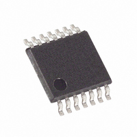
MAX5483EUD+ Maxim Integrated Products, MAX5483EUD+ Datasheet

MAX5483EUD+
Specifications of MAX5483EUD+
Related parts for MAX5483EUD+
MAX5483EUD+ Summary of contents
Page 1
... Denotes a lead(Pb)-free/RoHS-compliant package Exposed pad. Ordering Information continued at end of data sheet. ________________________________________________________________ Maxim Integrated Products For pricing delivery, and ordering information please contact Maxim Direct at 1-888-629-4642, or visit Maxim’s website at www.maxim-ic.com. ♦ 1024 Tap Positions ♦ Power-On Recall of Wiper Position from Nonvolatile Memory ♦ ...
Page 2
Nonvolatile, Linear-Taper Digital Potentiometers ABSOLUTE MAXIMUM RATINGS V to GND ...........................................................-0.3V to +6. GND............................................................-3.5V to +0. .............................................................-0.3V to +6. ..................................( CS, SCLK(INC), DIN(U/D), ...
Page 3
Nonvolatile, Linear-Taper Digital ELECTRICAL CHARACTERISTICS (continued +2.7V to +5.25V 0V, V GND +5.0V +25°C, unless otherwise noted.) (Note PARAMETER SYMBOL Full-Scale Wiper-to-End Resistance Zero-Scale ...
Page 4
Nonvolatile, Linear-Taper Digital Potentiometers TIMING CHARACTERISTICS (V = +2.7V to +5.25V 0V, V GND +5.0V +25°C, unless otherwise noted.) (Note PARAMETER SYMBOL ANALOG SECTION Wiper Settling ...
Page 5
Nonvolatile, Linear-Taper Digital (V = 5.0V 0V +25°C, unless otherwise noted DNL vs. CODE (MAX5483) 1 2.7V DD 0.8 0.6 0.4 0.2 0 -0.2 -0.4 -0.6 -0.8 -1.0 0 128 ...
Page 6
Nonvolatile, Linear-Taper Digital Potentiometers (V = 5.0V 0V +25°C, unless otherwise noted DNL vs. CODE (MAX5484) 1 2.7V DD 0.8 0.6 0.4 0.2 0 -0.2 -0.4 -0.6 -0.8 -1.0 0 ...
Page 7
Nonvolatile, Linear-Taper Digital (V = 5.0V 0V +25°C, unless otherwise noted WIPER RESISTANCE vs. CODE (VARIABLE RESISTOR +25° 128 ...
Page 8
Nonvolatile, Linear-Taper Digital Potentiometers (Circuit of Figure +25°C, unless otherwise noted.) A TAP-TO-TAP SWITCHING TRANSIENT RESPONSE (MAX5481 10pF W FROM CODE 01 1111 1111 TO CODE 10 0000 0000 1μs/div WIPER ...
Page 9
Nonvolatile, Linear-Taper Digital (MAX5481/MAX5482 Voltage-Dividers) PIN NAME TQFN TSSOP 4– N. SPI/ DIN(U/ SCLK(INC) ...
Page 10
Nonvolatile, Linear-Taper Digital Potentiometers (MAX5483/MAX5484 Variable Resistors) PIN NAME TQFN TSSOP 4– N. D.N. SPI/ DIN(U/D) 11 ...
Page 11
Nonvolatile, Linear-Taper Digital V DD 10-BIT GND NV MEMORY SPI SCLK(INC) INTERFACE DIN(U/D) UP/DOWN INTERFACE NOTE: THE MAX5481/MAX5482 ARE NOT INTENDED FOR CURRENT TO FLOW THROUGH THE WIPER (SEE THE MAX5481/MAX5482 PROGRAMMABLE VOLTAGE-DIVIDER SECTION). ______________________________________________________________________________________ Potentiometers ...
Page 12
Nonvolatile, Linear-Taper Digital Potentiometers V DD GND SCLK(INC) INTERFACE DIN(U/D) UP/DOWN INTERFACE Detailed Description The MAX5481/MAX5482 linear programmable voltage- dividers and the MAX5483/MAX5484 variable resistors feature 1024 tap points (10-bit resolution) (see the Functional Diagrams ). ...
Page 13
Nonvolatile, Linear-Taper Digital 128 256 384 512 640 CODE (DECIMAL) 50kΩ DEVICE SCALES BY A FACTOR OF FIVE Figure 1. Resistance from vs. Code (10k ...
Page 14
Nonvolatile, Linear-Taper Digital Potentiometers Table 2. Command Decoding* CLOCK EDGE Bit Name — — C1 Write Wiper Register Copy Wiper Register Register Copy NV Register ...
Page 15
Nonvolatile, Linear-Taper Digital a) 24-BIT COMMAND/DATA WORD CS SCLK(INC DIN(U/D) b) 8-BIT COMMAND WORD CS SCLK(INC DIN(U/D) Figure 4. Serial SPI-Compatible Interface Format CS 1 ...
Page 16
Nonvolatile, Linear-Taper Digital Potentiometers Table 3. Truth Table CS DIN(U/D) SCLK(INC) ↓ ↓ ↑ ↓ ↑ ↑ ↑ = Low-to-high transition. ↓ = High-to-low ...
Page 17
Nonvolatile, Linear-Taper Digital The MAX5481–MAX5484 feature a low-power standby mode. When the device is not being programmed, it enters into standby mode and supply current drops to 0.5µA (typ). Nonvolatile Memory The internal EEPROM consists of a nonvolatile register ...
Page 18
Nonvolatile, Linear-Taper Digital Potentiometers 5V H MAX5481 MAX5482 W MAX480 L Figure 9. Positive LCD Bias Control Using a Voltage-Divider 5V MAX480 MAX5483 MAX5484 W L Figure 10. Positive LCD Bias Control Using a Variable Resistor Programmable Filter Figure ...
Page 19
... FUNCTIONAL DIAGRAM Chip Information PROCESS: BiCMOS ______________________________________________________________________________________ Ordering Information (continued) PART END-TO-END RESISTANCE (kΩ) MAX5482ETE+ 10 MAX5482EUD+ 10 MAX5483ETE+ 50 MAX5483EUD+ 50 MAX5484ETE+ 10 MAX5484EUD+ 10 Note: All devices are specified over the -40°C to +85°C operating temperature range Denotes a lead(Pb)-free/RoHS-compliant package Exposed pad. Pin Configurations (continued) 14 ...
Page 20
... Maxim cannot assume responsibility for use of any circuitry other than circuitry entirely embodied in a Maxim product. No circuit patent licenses are implied. Maxim reserves the right to change the circuitry and specifications without notice at any time. 20 ____________________Maxim Integrated Products, 120 San Gabriel Drive, Sunnyvale, CA 94086 408-737-7600 © 2010 Maxim Integrated Products DESCRIPTION Maxim is a registered trademark of Maxim Integrated Products, Inc ...


