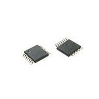
MAX5387LAUD+ Maxim Integrated Products, MAX5387LAUD+ Datasheet

MAX5387LAUD+
Specifications of MAX5387LAUD+
Related parts for MAX5387LAUD+
MAX5387LAUD+ Summary of contents
Page 1
... End-to-End Resistance Values C-Compatible Interface S Power-On Sets Wiper to Midscale S -40NC to + 125NC Operating Temperature Range S Applications PART MAX5387LAUD+ MAX5387MAUD+ MAX5387NAUD+ Note: All devices are specified over the -40NC to +125NC oper- ating temperature range. +Denotes a lead(Pb)-free/RoHS-compliant package LATCH 256 DECODER ...
Page 2
Dual, 256-Tap, Volatile, Low-Voltage Linear Taper Digital Potentiometer ABSOLUTE MAXIMUM RATINGS V to GND ...........................................................-0.3V to +6V DD H_, W_ GND ......................................-0.3V to the lower of All Other Pins to GND .............................................-0.3V to +6V Continuous Current into H_, ...
Page 3
Dual, 256-Tap, Volatile, Low-Voltage Linear Taper Digital Potentiometer ELECTRICAL CHARACTERISTICS (continued +2.6V to +5.5V +25NC.) (Note 1) A PARAMETER SYMBOL AC PERFORMANCE Crosstalk -3dB Bandwidth Total Harmonic ...
Page 4
Dual, 256-Tap, Volatile, Low-Voltage Linear Taper Digital Potentiometer Note 5: Drive HA with a 1kHz GND to V Measure WB. Note 6: The wiper settling time is the worst-case 0 to 50% rise time, measured between tap 0 and tap ...
Page 5
Dual, 256-Tap, Volatile, Low-Voltage Linear Taper Digital Potentiometer ( +25°C, unless otherwise noted WIPER RESISTANCE vs. WIPER VOLTAGE (10k I ) 210 190 V = 2.6V DD 170 150 130 DD ...
Page 6
Dual, 256-Tap, Volatile, Low-Voltage Linear Taper Digital Potentiometer ( +25°C, unless otherwise noted VOLTAGE-DIVIDER DNL vs. TAP POSITION (50kI) 0.10 0.08 0.06 0.04 0.02 0 -0.02 -0.04 -0.06 -0.08 -0. 102 153 ...
Page 7
Dual, 256-Tap, Volatile, Low-Voltage Linear Taper Digital Potentiometer ( +25°C, unless otherwise noted MAX5387 POWER-ON WIPER TRANSIENT (CODE 0 TO 128) 2µs/div CROSSTALK vs. FREQUENCY 0 -20 -40 -60 -80 -100 MAX5387N -120 -140 ...
Page 8
Dual, 256-Tap, Volatile, Low-Voltage Linear Taper Digital Potentiometer PIN NAME Resistor A High Terminal. The voltage at HA can be higher or lower than the voltage at LA. Current 1 HA can flow into or out of HA ...
Page 9
Dual, 256-Tap, Volatile, Low-Voltage Linear Taper Digital Potentiometer Detailed Description The MAX5387 dual, 256-tap, volatile, low-voltage linear taper digital potentiometer offers three end-to-end resis- tance values of 10kI, 50kI, and 100kI. The potenti- ometer consists of 255 fixed resistors in ...
Page 10
Dual, 256-Tap, Volatile, Low-Voltage Linear Taper Digital Potentiometer One data bit is transferred during each clock pulse. The data on the SDA line must remain stable while SCL is high. See Figure 4. The acknowledge bit is a clocked 9th ...
Page 11
Dual, 256-Tap, Volatile, Low-Voltage Linear Taper Digital Potentiometer SDA 0 1 START MSB SCL Figure 6. Slave Address HOW CONTROL BYTE AND DATA BYTE MAP INTO DEVICE REGISTERS ACKNOWLEDGE S SLAVE ADDRESS NOP/W Figure 7. Command and Single Data Byte ...
Page 12
Dual, 256-Tap, Volatile, Low-Voltage Linear Taper Digital Potentiometer 2 Table Command Byte Summary ADDRESS BYTE SCL CYCLE NO REG ...
Page 13
Dual, 256-Tap, Volatile, Low-Voltage Linear Taper Digital Potentiometer Variable Gain Current to Voltage Converter Figure 12 shows a variable gain current to voltage con- verter using a potentiometer as a variable resistor. LCD Bias Control Figure 13 shows a positive ...
Page 14
Dual, 256-Tap, Volatile, Low-Voltage Linear Taper Digital Potentiometer Figure 15. Programmable Filter Process Information PROCESS: BiCMOS 14 _____________________________________________________________________________________ V OUT R1 Figure 16. Offset-Voltage Adjustment Circuit For the latest package ...
Page 15
... Maxim cannot assume responsibility for use of any circuitry other than circuitry entirely embodied in a Maxim product. No circuit patent licenses are implied. Maxim reserves the right to change the circuitry and specifications without notice at any time. Maxim Integrated Products, 120 San Gabriel Drive, Sunnyvale, CA 94086 408-737-7600 2010 Maxim Integrated Products © ...


