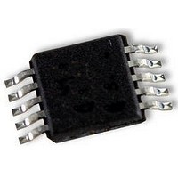
AD5174BRMZ-10 Analog Devices Inc, AD5174BRMZ-10 Datasheet

AD5174BRMZ-10
Specifications of AD5174BRMZ-10
Available stocks
Related parts for AD5174BRMZ-10
AD5174BRMZ-10 Summary of contents
Page 1
FEATURES Single-channel, 1024-position resolution 10 kΩ nominal resistance 50-times programmable (50-TP) wiper memory Rheostat mode temperature coefficient: 35 ppm/°C 2 5.5 V single-supply operation ±2 ±2.75 V dual-supply operation for ac or bipolar operations SPI-compatible interface ...
Page 2
AD5174 TABLE OF CONTENTS Features .............................................................................................. 1 Applications....................................................................................... 1 Functional Block Diagram .............................................................. 1 General Description ......................................................................... 1 Revision History ............................................................................... 2 Specifications..................................................................................... 3 Electrical Characteristics............................................................. 3 Interface Timing Specifications.................................................. 4 Absolute Maximum Ratings............................................................ 6 Thermal Resistance ...................................................................... 6 ESD ...
Page 3
SPECIFICATIONS ELECTRICAL CHARACTERISTICS Table 1. Parameter DC CHARACTERISTICS—RHEOSTAT MODE Resolution 2, 3 Resistor Integral Nonlinearity 2 Resistor Differential ...
Page 4
AD5174 Parameter 4, 10 DYNAMIC CHARACTERISTICS Bandwidth Total Harmonic Distortion Resistor Noise Density 1 Typical specifications represent average readings at 25° Resistor position nonlinearity error (R-INL) is the deviation from an ideal value measured between the maximum resistance ...
Page 5
Shift Register and Timing Diagrams CONTROL BITS SCLK SYNC DIN SDO SCLK SYNC DIN SDO DB9 (MSB ...
Page 6
AD5174 ABSOLUTE MAXIMUM RATINGS T = 25°C, unless otherwise noted. A Table 3. Parameter V to GND GND GND A W Digital Input and Output Voltage to ...
Page 7
PIN CONFIGURATION AND FUNCTION DESCRIPTIONS SYNC 10 DD AD5174 SCLK DIN TOP VIEW SDO SS (Not to Scale) EXT_CAP 5 GND 6 Figure 5. MSOP ...
Page 8
AD5174 TYPICAL PERFORMANCE CHARACTERISTICS 0.8 +25°C –40°C 0.6 +125°C 0.4 0.2 0 –0.2 –0.4 –0.6 0 128 256 384 512 640 CODE (Decimal) Figure 7. R-INL vs. Code vs. Temperature 0.4 +25°C –40°C 0.3 +125°C 0.2 0.1 0 –0.1 –0.2 ...
Page 9
V – 100 1k 10k 100k FREQUENCY (Hz) Figure 13. Bandwidth vs. Frequency vs. Code ...
Page 10
AD5174 1.0 0.5 0 –0.5 –1.0 –1.5 – TIME (µs) Figure 19. Digital Feedthrough 0.006 0.005 0.004 0.003 0.002 0.001 0 –0.001 ±2. 200µA AW –0.002 ...
Page 11
TEST CIRCUITS Figure 21 to Figure 25 define the test conditions used in the Specifications section. DUT Figure 21. Resistor Position Nonlinearity Error (Rheostat Operation; R-INL, R-DNL CODE = 0x00 DUT I ...
Page 12
AD5174 THEORY OF OPERATION The AD5174 is designed to operate as a true variable resistor for analog signals within the terminal voltage range of V < The RDAC register contents determine the resistor wiper DD position. The RDAC ...
Page 13
RDAC AND 50-TP READ OPERATION A serial data output SDO pin is available for readback of the internal RDAC register or 50-TP memory contents. The contents of the RDAC register can be read back through SDO by using Command 2 ...
Page 14
AD5174 SHUTDOWN MODE The AD5174 can be shut down by executing the software shutdown command, Command 9 (see Table 6), and setting the LSB to 1. This feature places the RDAC in a zero-power- consumption state where Terminal A is ...
Page 15
Table 10. Memory Map Command Number … … … … … … … … … … … ...
Page 16
AD5174 RDAC ARCHITECTURE To achieve optimum performance, Analog Devices, Inc., has patented the RDAC segmentation architecture for all the digital potentiometers. In particular, the AD5174 employs a three-stage segmentation approach as shown in Figure 27. The AD5174 wiper switch is ...
Page 17
EXT_CAP CAPACITOR A 1 μF capacitor to V must be connected to the EXT_CAP SS pin, as shown in Figure 28, on power-up and throughout the operation of the AD5174. AD5174 50-TP MEMORY EXT_CAP BLOCK C1 1µ ...
Page 18
... AD5174 OUTLINE DIMENSIONS PIN 1 INDEX AREA 0.80 0.75 0.70 SEATING PLANE IDENTIFIER ORDERING GUIDE Model 1 R (kΩ) Resolution AB AD5174BRMZ-10 10 1,024 AD5174BRMZ-10-RL7 10 1,024 AD5174BCPZ-10-RL7 10 1,024 RoHS Compliant Part. 3.10 3.00 SQ 2.90 6 0.50 0.40 0.30 5 TOP VIEW BOTTOM VIEW 0.05 MAX 0.02 NOM ...
Page 19
NOTES Rev Page AD5174 ...
Page 20
AD5174 NOTES ©2010 Analog Devices, Inc. All rights reserved. Trademarks and registered trademarks are the property of their respective owners. D08718-0-12/10(B) Rev Page ...


