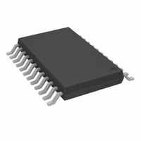
AD5233BRUZ50-R7 Analog Devices Inc, AD5233BRUZ50-R7 Datasheet - Page 24

AD5233BRUZ50-R7
Manufacturer Part Number
AD5233BRUZ50-R7
Description
IC DGTL POT QUAD 64POS 24-TSSOP
Manufacturer
Analog Devices Inc
Datasheet
1.AD5233BRUZ10-R7.pdf
(32 pages)
Specifications of AD5233BRUZ50-R7
Taps
64
Resistance (ohms)
50K
Number Of Circuits
4
Temperature Coefficient
600 ppm/°C Typical
Memory Type
Non-Volatile
Interface
4-Wire SPI Serial
Voltage - Supply
2.7 V ~ 5.5 V, ±2.25 V ~ 2.75 V
Operating Temperature
-40°C ~ 85°C
Mounting Type
Surface Mount
Package / Case
24-TSSOP
Resistance In Ohms
50K
Number Of Elements
4
# Of Taps
64
Resistance (max)
50KOhm
Power Supply Requirement
Single/Dual
Interface Type
Serial (4-Wire/SPI)
Single Supply Voltage (typ)
3/5V
Dual Supply Voltage (typ)
±2.5V
Single Supply Voltage (min)
2.7V
Single Supply Voltage (max)
5.5V
Dual Supply Voltage (min)
±2.25V
Dual Supply Voltage (max)
±2.75V
Operating Temp Range
-40C to 85C
Operating Temperature Classification
Industrial
Mounting
Surface Mount
Pin Count
24
Lead Free Status / RoHS Status
Lead free / RoHS Compliant
AD5233
BIPOLAR PROGRAMMABLE GAIN AMPLIFIER
There are several ways to achieve bipolar gain. Figure 50 shows
one versatile implementation. Digital potentiometer, U1, sets
the adjustment range; therefore, the wiper voltage, V
programmed between V
Configuring A2 as a noninverting amplifier yields a linear
transfer function:
where:
K is the ratio of R
D is the decimal equivalent of the input code.
In the simpler (and much more usual) case where K is 1, a
pair of matched resistors can replace U1. Equation 4 can be
simplified to
Table 19 shows the result of adjusting D with A2 configured as a
unity gain, a gain of 2, and a gain of 10. The result is a bipolar
amplifier with linearly programmable gain and 64-step resolution.
Table 19. Result of Bipolar Gain Amplifier
D
0
16
32
48
63
V
V
V
V
V
i
AD5233
O
O
i
i
=
=
AD5233
⎛ +
⎜
⎝
⎛ +
⎜
⎝
Figure 50. Bipolar Programmable Gain Amplifier
1
1
R1 = ∞, R2 = 0
−1
−0.5
0
0.5
0.968
A2
U1
R2
U2
A1
R2
R1
R1
WB
⎞
⎟
⎠
⎞
⎟
⎠
W2
/R
×
B1
W1
×
B2
A1
OP2177
⎛
⎜
⎝
WA
⎛
⎜
⎝
2
D2
64
i
V+
V–
64
D
that is set by U1.
and −KV
V
V
DD
SS
2
×
−
1 (
1
+
⎞
⎟
⎠
K
R1 = R2
−2
−1
0
1
1.937
i
)
at a given U2 setting.
–KV
−
i
K
A2
OP2177
⎞
⎟
⎠
V+
V–
V
V
DD
SS
R2
R1
R2 = 9 × R1
−10
−5
0
5
9.680
W2
V
O
, can be
C
Rev. B | Page 24 of 32
(4)
(5)
PROGRAMMABLE LOW-PASS FILTER
The AD5233 digital potentiometer can be used to construct a
second-order Sallen-Key low-pass filter, as shown in Figure 51.
The design equations are
where:
Q is the Q factor.
V
R1 and R2 are R
To achieve maximal flat bandwidth where Q is 0.707, let C1
be twice the size of C2 and let R1 equal R2. Users can first
select convenient values for the capacitors and then gang and
move R1 and R2 together to adjust the −3 dB corner frequency.
Instruction 5, Instruction 7, Instruction 13, and Instruction 15
of the AD5233 make these changes simple to implement.
O
is the resonant frequency.
V
ω
Q
V
V
i
O
O
i
=
=
=
R1
S
A
×
R
2
R1
1
TOGETHER
R1
GANGED
+
C1
W
×
WB1
B
ω
Figure 51. Sallen-Key Low-Pass Filter
Q
ω
R2
+
O
O
and R
R2
S
2
1
×
A
R
+
C1
R2
×
1
ω
W
C2
C2
B
O
×
WB2
2
C2
, respectively.
C1
AD8601
+2.5V
–2.5V
V+
V–
U1
V
O
(6)
(7)
(8)


