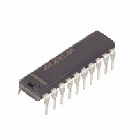
DS1802+ Maxim Integrated Products, DS1802+ Datasheet

DS1802+
Specifications of DS1802+
Related parts for DS1802+
DS1802+ Summary of contents
Page 1
FEATURES § Ultra- low power consumption § Operates from supplies § Two digitally controlled, 65-position potentiometers including mute § Logarithmic resistive characteristics (1 dB per step) § Zero-crossing detection eliminates noise caused by wiper movement § ...
Page 2
DESCRIPTION The DS1802 is a dual audio taper-potentiometer having logarithmic resistive characteristics over the device range. Each potentiometer provides 65 wiper positions with increment per step and device mute. The DS1802 has two methods of device control, ...
Page 3
DS1802 BLOCK DIAGRAM Figure 1 CONTACT CLOSURE INTERFACE CONTROL The DS1802 can be configured to operate from contact closure inputs sometimes referred to as pushbutton control. There exists a total of four physical contact closure terminals on the device package. ...
Page 4
Independent mode control allows the user to independently control each potentiometer's wiper position. For independent mode control, the MODE input should high state. For stereo mode control, the MODE input should low state. The ...
Page 5
SINGLE PUSHBUTTON CONFIGURATION Figure 2(a) DUAL PUSHBUTTON CONFIGURATION Figure 2(b) Contact closure is defined as the transition from a high level to a low level on the contact closure input terminals. The DS1802 interprets input pulse widths as the means ...
Page 6
Pulse inputs lasting longer than 1 second will cause the wiper to move one position every 100 ms following the initial 1 second hold time. The total time to transcend the entire potentiometer using a continuous input pulse is given ...
Page 7
DS1802 BALANCING EXAMPLE Figure 3 CONTACT CLOSURE TIMING (UC, DC) Figure 4 Dual Contact Closure In dual pushbutton mode, each direction is controlled by the respective cont rol inputs. No wait states are required to change wiper direction, balance, or ...
Page 8
All contact closure control inputs, UC0, UC1, DC0, DC1, VU, VD, B0 and B1 are internally pulled resistance. The UC0, UC1, DC0 DC1, VU, VD, B0, and B1 inputs are internally debounced and require no ...
Page 9
I/O SHIFT REGISTER Figure 5 TIMING DIAGRAMS Figure DS1802 ...
Page 10
CASCADE OPERATION A feature of the DS1802 is the ability to control multiple devices from a single processor. Multiple DS1802s can be linked or daisy-chained as shown in Figure bit is entered in to the I/O shift ...
Page 11
Subsequent changes when operating with continuous input pulse occur on 100 ms time intervals and are dependent on zero-crossing timeouts. MUTE CONTROL The DS1802 provides a mute control feature which can be accessed by the ...
Page 12
TYPICAL SUPPLY CURRENT VS. SERIAL CLOCK RATE Figure DS1802 ...
Page 13
ABSOLUTE MAXIMUM RATINGS* Voltage on Any Pin Relative to Ground Operating Temperature Storage Temperature Soldering Temperature * This is a stress rating only and functional operation of the device at these or any other conditions above those indicated in the ...
Page 14
ANALOG RESISTOR CHARACTERISTICS PARAMETER End to End Resistor Tolerance Absolute Tolerance Inter-channel Matching Tap-to-Tap Tolerance -3 dB Cutoff Frequency Temperature Coefficient Total Harmonic Distortion (V = kHz, Tap = -6 IN RMS dB) Output Noise ( ...
Page 15
AC ELECTRICAL CHARACTERISTICS PARAMETER CLK Frequency Width of CLK Pulse Data Setup Time Data Hold Time Propagation Delay Time Low to High Level Clock to Output Propagation Delay Time Low to High Level High to Clock Input High RST Low ...
Page 16
Tap-to-tap tolerance is used to determine the change in voltage between successive tap positions. The DS1802 is specified for 0.25 dB tap-to-tap tolerance. 8. Typical values are for t =25 C and no minal supply voltage Power-up ...
Page 17
INTERNAL GROUND CONNECTIONS Figure 10 NOTE: GND and AGND must be tied to the same voltage level DS1802 ...


