X9314WM Intersil, X9314WM Datasheet
X9314WM
Specifications of X9314WM


Related parts for X9314WM

X9314WM Summary of contents
Page 1
... CAUTION: These devices are sensitive to electrostatic discharge; follow proper IC Handling Procedures. | 1-888-INTERSIL or 1-888-468-3774 Intersil (and design registered trademark of Intersil Americas Inc. XDCP is a trademark of Intersil Americas Inc. Copyright Intersil Americas Inc. 2005, 2006. All Rights Reserved All other trademarks mentioned are the property of their respective owners. X9314 FN8178.2 ...
Page 2
... X9314W I X9314WSIZ (Note) X9314W ZI X9314WSZ* (Note) X9314W Z X9314WMI-3* AAY X9314WMIZ-3* (Note) DEX X9314WS-3* X9314W D X9314WSZ-3* (Note) X9314W ZD *Add "T1" suffix for tape and reel. NOTE: Intersil Pb-free plus anneal products employ special Pb-free material sets; molding compounds/die attach materials and 100% matte tin plate termination finish, which are RoHS compliant and compatible with both SnPb and Pb-free soldering operations ...
Page 3
Typical Attenuation Characteristics (dB) 0 -20 -40 -43.5 - Principles of Operation There are three sections of the X9314: the input control, counter and decode section; the nonvolatile memory; and the resistor array. The input control section ...
Page 4
Absolute Maximum Ratings Temperature under bias . . . . . . . . . . . . . . . . . . . . . .-65°C to +135°C Storage temperature . . . . . . . . ...
Page 5
DC Electrical Specifications (Over recommended operating conditions unless otherwise specified.) SYMBOL PARAMETER I V Active Current Standby Supply Current SB I CS, INC, U/D Input Leakage Current LI V CS, INC, U/D Input HIGH Voltage IH V ...
Page 6
AC Electrical Specifications (Over recommended operating conditions unless otherwise specified) SYMBOL INC Setup Cl t INC HIGH to U/D Change lD t U/D to INC Setup DI t INC LOW Period lL t INC HIGH Period lH ...
Page 7
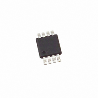
Mini Small Outline Plastic Packages (MSOP -B- INDEX 1 2 0.20 (0.008) AREA TOP VIEW 0.25 (0.010) GAUGE PLANE SEATING PLANE - 0.10 (0.004) b -H- - 0.20 (0.008) SIDE VIEW 0.20 ...
Page 8
Small Outline Plastic Packages (SOIC) N INDEX 0.25(0.010) H AREA E - SEATING PLANE - -C- α 0.10(0.004) 0.25(0.010 NOTES: 1. Symbols are defined in the ...
Page 9
... Accordingly, the reader is cautioned to verify that data sheets are current before placing orders. Information furnished by Intersil is believed to be accurate and reliable. However, no responsibility is assumed by Intersil or its subsidiaries for its use; nor for any infringements of patents or other rights of third parties which may result from its use ...