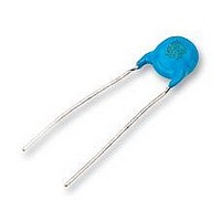
DE1E3KX472MA5B Murata, DE1E3KX472MA5B Datasheet

DE1E3KX472MA5B
Specifications of DE1E3KX472MA5B
Available stocks
Related parts for DE1E3KX472MA5B
DE1E3KX472MA5B Summary of contents
Page 1
... Part Numbering Safety Standard Recognized Ceramic Capacitors (Part Number qProduct ID Product ID High Voltage (250V - 6.3kV Safety Standard Recognized Ceramic Capacitors wSeries Category Code Outline IEC60384-14 Class X1 Safety Standard Recognized IEC60384-14 Class X1 "Products which are based on AC250V the Electrical Appliance and J (r.m.s.) Material Safety Law of Japan" ...
Page 2
Taping Specifications 12.7mm pitch / lead spacing 5mm taping Vertical crimp type (Lead Code : N2 ø ø 15mm pitch / lead spacing 7.5mm taping Straight type (Lead ...
Page 3
Continued from the preceding page. Packaging Styles Bulk Polyethylene Bag Ammo Pack Minimum Quantity (Order in Sets Only) [Bulk] 1,000 pcs. [Taping] Lead Code Type KY Type KH N2 1,000 – N3, P3 900 900 N7 – 400 N4, N5 ...
Page 4
... Operating Voltage When DC-rated capacitors are to be used ripple current circuits, be sure to maintain the Vp-p value of the applied voltage or the Vo-p which contains DC bias within the rated voltage range. When the voltage is applied to the circuit, starting or stopping may generate irregular voltage for a transit period because of resonance or switching ...
Page 5
Continued from the preceding page. (2) Voltage Applied Method When the withstanding voltage is applied, capacitor's lead or terminal should be firmly connected to the output of the withstanding voltage test equipment, and then the voltage should be raised from ...
Page 6
Specifications and Test Methods Apply to Type KY/KH/KX Operating Temperature Range : -25 to +125°C (-25 to +85°C in case of the standard of UL) No. Item No marked defect on appearance form and 1 Appearance and Dimensions dimensions are ...
Page 7
Continued from the preceding page. No. Item Appearance No marked defect Capacitance Within ±10% Change I.R. 1000MΩ min. Soldering 9 Effect (Non-Preheat) Dielectric Per Item 6 Strength Appearance No marked defect Capacitance Within ±10% Change I.R. 1000MΩ min. Soldering 10 ...
Page 8
... The cheese-cloth should not be on fire "C" expresses nominal capacitance value (pF "room condition" Temperature 35°C, Relative humidity 75%, Atmospheric pressure 106kPa Specifications Impulse Voltage Each individual capacitor should be subjected to a 5kV (Type KX: 8kV) impulses for three times. After the capacitors are applied to life test. 100 (%) Apply a voltage of Table 4 for 1000 hrs. at 125+2/-0° ...
Page 9
Specifications and Test Methods Continued from the preceding page. No. Item The burning time should not exceed 30 sec. 18 Passive Flammability The tissue paper should not ignite. Appearance No marked defect Char. Capacitance Change SL Char. ...
Page 10
Type KX (B char.) AC voltage : 60Hz Temperature : 25 C 1.2 1.0 0.8 0.6 0.4 0.2 0.0 0 1000 2000 3000 AC voltage [V(r.m.s.)] Type KX (E char.) AC voltage Temperature : 25 C 6.0 5.0 4.0 3.0 ...


