DE1E3KX472MA5B Murata, DE1E3KX472MA5B Datasheet - Page 6
DE1E3KX472MA5B
Manufacturer Part Number
DE1E3KX472MA5B
Description
CAPACITOR, X1/Y1 4.7NF CAPACITOR, X1/Y1 4.7NF
Manufacturer
Murata
Series
KXr
Datasheet
1.DE1B3KX101KA5B.pdf
(10 pages)
Specifications of DE1E3KX472MA5B
Capacitance
4700PF
Capacitor Dielectric Type
CERAMIC DISC AND PLATE
Tolerance,
20%
Tolerance, -
20%
Temp, Op. Max
125(DEGREE C)
Temp, Op. Min
-25(DEGREE C)
Pitch,
ROHS COMPLIANT
Available stocks
Company
Part Number
Manufacturer
Quantity
Price
Company:

Part Number:
DE1E3KX472MA5BA01
Manufacturer:
MURATA
Quantity:
21 000
Company:
Part Number:
DE1E3KX472MA5BA01
Manufacturer:
MURATA
Quantity:
8 100


Operating Temperature Range : -25 to +125°C (-25 to +85°C in case of the standard of UL)
No.
*
1
2
3
4
5
6
7
8
Specifications and Test Methods
1
Apply to Type KY/KH/KX
"C" expresses nominal capacitance value (pF).
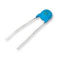
Appearance and Dimensions
Marking
Capacitance
Dissipation Factor (D.F.)
Q
Insulation Resistance (I.R.)
Dielectric
Strength
Temperature Characteristics
Solderability of Leads
Item
Between Lead
Wires
Body
Insulation
No marked defect on appearance form and
dimensions are within specified range.
To be easily legible
Within specified tolerance
10000MΩ min.
No failure
No failure
Temperature characteristic guarantee is -25 to +85°C
Temperature characteristic guarantee is +20 to +85°C
Lead wire should be soldered with uniform coating
on the axial direction over 3/4 of the circumferential
direction.
Char.
Char.
Char.
B, E
SL
SL
B
E
F
F
Temperature Coefficient
QU1000
QU400+20C
Capacitance Change
+350 to -1000ppm/°C
Specifications
Specifications
Within ±10%
Within
Within
D.F.V2.5%
D.F.V5.0%
+20
+30
*1
-55
-80
(CF30pF)
(CU30pF)
%
%
The capacitor should be visually inspected for evidence of
defect.
Dimensions should be measured with slide calipers.
The capacitor should be visually inspected.
The capacitance, dissipation factor and Q should be measured
at 20˚C with 1±0.1kHz (char. SL : 1±0.1MHz) and AC5V
(r.m.s.) max.
The insulation resistance should be measured with
DC500±50V within 60±5 sec. of charging.
The voltage should be applied to the capacitor through a
resistor of 1MΩ.
The capacitor should not be damaged when test voltages of
Table 1 are applied between the lead wires for 60 sec.
First, the terminals of the capacitor
should be connected together. Then,
as shown in figure at right, a metal
foil should be closely wrapped around
the body of the capacitor to the
distance of about 3 to 4mm from
each terminal.
Then, the capacitor should be inserted
of about 1mm diameter. Finally, AC
voltage of Table 2 is applied for 60 sec. between the capacitor
lead wires and metal balls.
The capacitance measurement should be made at each step
specified in Table 3.
The lead wire of a capacitor should be dipped into molten
solder for 2±0.5 sec.
The depth of immersion is up to about 1.5 to 2.0mm from the
root of lead wires.
Temp. of solder: Lead Free Solder (Sn-3Ag-0.5Cu) 245±5°C
into a container filled with metal balls
Type
Type
Step
KH
KH
KY
KX
KY
KX
1
2
3
4
5
In case of lead spacing F=5mm AC2000V (r.m.s.)
In case of lead spacing F=7.5mm AC2600V (r.m.s.)
<Table.2>
H63 Eutectic Solder 235±5°C
<Table.3>
AC2600V (r.m.s.)
AC2600V (r.m.s.)
AC4000V (r.m.s.)
Temperature (ºC)
Test Voltage
Testing Method
-25±2
20±2
20±2
85±2
20±2
<Table.1>
AC2600V (r.m.s.)
AC4000V (r.m.s.)
Continued on the following page.
Test Voltage
Metal
Foil
about
3 to 4mm
Metal
Balls
Related parts for DE1E3KX472MA5B
Image
Part Number
Description
Manufacturer
Datasheet
Request
R

Part Number:
Description:
Murata Microblower 20x20 DCDC Driver Board - Samples Only
Manufacturer:
Murata
Part Number:
Description:
357-036-542-201 CARDEDGE 36POS DL .156 BLK LOPRO
Manufacturer:
Murata
Datasheet:
Part Number:
Description:
Manufacturer:
Murata
Datasheet:
Part Number:
Description:
Manufacturer:
Murata
Datasheet:
Part Number:
Description:
Manufacturer:
Murata
Datasheet:
Part Number:
Description:
Manufacturer:
Murata
Datasheet:
Part Number:
Description:
Manufacturer:
Murata
Datasheet:
Part Number:
Description:
Manufacturer:
Murata
Datasheet:
Part Number:
Description:
Manufacturer:
Murata
Datasheet:
Part Number:
Description:
BLM21BD751SN1On-Board Type (DC) EMI Suppression Filters
Manufacturer:
Murata
Datasheet:
Part Number:
Description:
BLM15AG100SN1On-Board Type (DC) EMI Suppression Filters
Manufacturer:
Murata
Datasheet:
Part Number:
Description:
NFE31PT222Z1E9On-Board Type (DC) EMI Suppression Filters
Manufacturer:
Murata
Datasheet:
Part Number:
Description:
Chip Coil
Manufacturer:
Murata
Datasheet:
Part Number:
Description:
Chip Coil
Manufacturer:
Murata
Datasheet: