DE1E3KX472MA5B Murata, DE1E3KX472MA5B Datasheet - Page 7
DE1E3KX472MA5B
Manufacturer Part Number
DE1E3KX472MA5B
Description
CAPACITOR, X1/Y1 4.7NF CAPACITOR, X1/Y1 4.7NF
Manufacturer
Murata
Series
KXr
Datasheet
1.DE1B3KX101KA5B.pdf
(10 pages)
Specifications of DE1E3KX472MA5B
Capacitance
4700PF
Capacitor Dielectric Type
CERAMIC DISC AND PLATE
Tolerance,
20%
Tolerance, -
20%
Temp, Op. Max
125(DEGREE C)
Temp, Op. Min
-25(DEGREE C)
Pitch,
ROHS COMPLIANT
Available stocks
Company
Part Number
Manufacturer
Quantity
Price
Company:

Part Number:
DE1E3KX472MA5BA01
Manufacturer:
MURATA
Quantity:
21 000
Company:
Part Number:
DE1E3KX472MA5BA01
Manufacturer:
MURATA
Quantity:
8 100


No.
10
11
12
13
*
*
9
1
2
"C" expresses nominal capacitance value (pF).
"room condition" Temperature: 15 to 35°C, Relative humidity: 45 to 75%, Atmospheric pressure: 86 to 106kPa
Continued from the preceding page.
Soldering
Effect
(Non-Preheat)
Soldering
Effect
(On-Preheat)
Vibration
Resistance
Humidity
(Under
Steady
State)
Humidity
Loading
Item
Appearance
Capacitance
Change
I.R.
Dielectric
Strength
Appearance
Capacitance
Change
I.R.
Dielectric
Strength
Appearance
Capacitance
D.F.
Q
Appearance
Capacitance
Change
D.F.
Q
I.R.
Dielectric
Strength
Appearance
Capacitance
Change
D.F.
Q
I.R.
Dielectric
Strength
No marked defect
Within ±10%
1000MΩ min.
Per Item 6
No marked defect
Within ±10%
1000MΩ min.
Per Item 6
No marked defect
Within the specified tolerance
No marked defect
3000MΩ min.
Per Item 6
No marked defect
3000MΩ min.
Per Item 6
Char.
Char.
Char.
Char.
Char.
B, E
E, F
B, E
E, F
B, E
SL
SL
SL
SL
SL
B
B
F
F
F
QU275+5/2C
QU350
QU275+5/2C
QU350
QU1000
QU400+20C
Capacitance Change
Capacitance Change
Specifications
Specifications
Specifications
Specifications
Within ±10%
Within ±15%
Within ± 5%
Within ±10%
Within ±15%
Within ± 5%
D.F.V2.5%
D.F.V5.0%
D.F.V5.0%
D.F.V7.5%
D.F.V5.0%
D.F.V7.5%
*1
*1
*1
(CF30pF)
(CU30pF)
(CF30pF)
(CU30pF)
(CF30pF)
(CU30pF)
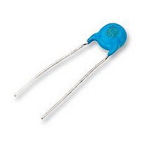
As shown in figure, the lead wires
should be immersed in solder of
350±10°C or 260±5°C up to 1.5
to 2.0mm from the root of terminal
for 3.5±0.5 sec. (10±1 sec. for
260±5°C).
Pre-treatment:
Post-treatment:
First the capacitor should be
stored at 120+0/-5°C for
60+0/-5 sec.
Then, as in figure, the lead wires
should be immersed solder of
260+0/-5°C up to 1.5 to 2.0mm
from the root of terminal for
7.5+0/-1 sec.
Pre-treatment:
Post-treatment:
The capacitor should be firmly soldered to the supporting lead
wire and vibrated at a frequency range of 10 to 55Hz, 1.5mm in
total amplitude, with about a 1 minute rate of vibration change
from 10Hz to 55Hz and back to 10Hz.
Apply for a total of 6 hrs., 2 hrs. each in 3 mutually
perpendicular directions.
Set the capacitor for 500±12 hrs. at 40±2°C in 90 to 95%
relative humidity.
Post-treatment:
Apply the rated voltage for 500±12 hrs. at 40±2°C in 90 to 95%
relative humidity.
Post-treatment:
Specifications and Test Methods
Capacitor should be stored at 85±2°C for 1 hr., then placed at
Capacitor should be stored for 1 to 2 hrs. at
Capacitor should be stored at 85±2°C for 1 hr., then placed at
Capacitor should be stored for 1 to 2 hrs. at
Capacitor should be stored for 1 to 2 hrs. at
Capacitor should be stored for 1 to 2 hrs. at
2
2
room condition for 24±2 hrs. before initial measurements.
room condition for 24±2 hrs. before initial measurements.
Testing Method
Continued on the following page.
Thermal
Screen
Thermal
Screen
2
2
2
2
room condition.
room condition.
room condition.
room condition.
Capacitor
Capacitor
Molten
Solder
Molten
Solder
1.5
to 2.0mm
1.5
to 2.0mm
Related parts for DE1E3KX472MA5B
Image
Part Number
Description
Manufacturer
Datasheet
Request
R

Part Number:
Description:
Murata Microblower 20x20 DCDC Driver Board - Samples Only
Manufacturer:
Murata
Part Number:
Description:
357-036-542-201 CARDEDGE 36POS DL .156 BLK LOPRO
Manufacturer:
Murata
Datasheet:
Part Number:
Description:
Manufacturer:
Murata
Datasheet:
Part Number:
Description:
Manufacturer:
Murata
Datasheet:
Part Number:
Description:
Manufacturer:
Murata
Datasheet:
Part Number:
Description:
Manufacturer:
Murata
Datasheet:
Part Number:
Description:
Manufacturer:
Murata
Datasheet:
Part Number:
Description:
Manufacturer:
Murata
Datasheet:
Part Number:
Description:
Manufacturer:
Murata
Datasheet:
Part Number:
Description:
BLM21BD751SN1On-Board Type (DC) EMI Suppression Filters
Manufacturer:
Murata
Datasheet:
Part Number:
Description:
BLM15AG100SN1On-Board Type (DC) EMI Suppression Filters
Manufacturer:
Murata
Datasheet:
Part Number:
Description:
NFE31PT222Z1E9On-Board Type (DC) EMI Suppression Filters
Manufacturer:
Murata
Datasheet:
Part Number:
Description:
Chip Coil
Manufacturer:
Murata
Datasheet:
Part Number:
Description:
Chip Coil
Manufacturer:
Murata
Datasheet: