DE1E3KX472MA5B Murata, DE1E3KX472MA5B Datasheet - Page 8

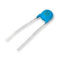
DE1E3KX472MA5B
Manufacturer Part Number
DE1E3KX472MA5B
Description
CAPACITOR, X1/Y1 4.7NF CAPACITOR, X1/Y1 4.7NF
Manufacturer
Murata
Series
KXr
Datasheet
1.DE1B3KX101KA5B.pdf
(10 pages)
Specifications of DE1E3KX472MA5B
Capacitance
4700PF
Capacitor Dielectric Type
CERAMIC DISC AND PLATE
Tolerance,
20%
Tolerance, -
20%
Temp, Op. Max
125(DEGREE C)
Temp, Op. Min
-25(DEGREE C)
Pitch,
ROHS COMPLIANT
Available stocks
Company
Part Number
Manufacturer
Quantity
Price
Company:
Part Number:
DE1E3KX472MA5BA01
Manufacturer:
MURATA
Quantity:
21 000
Company:
Part Number:
DE1E3KX472MA5BA01
Manufacturer:
MURATA
Quantity:
8 100
No.
14
15
16
17
*
*
Specifications and Test Methods
1
2
"C" expresses nominal capacitance value (pF).
"room condition" Temperature: 15 to 35°C, Relative humidity: 45 to 75%, Atmospheric pressure: 86 to 106kPa
Continued from the preceding page.
Life
Flame Test
Robustness
of
Terminations
Active Flammability
Item
Appearance
Capacitance
Change
I.R.
Dielectric
Strength
Tensile
Bending
No marked defect
Within ±20%
3000MΩ min.
Per Item 6
The capacitor flame discontinues as follows.
Lead wire should not be cut off. Capacitor should
not be broken.
The cheese-cloth should not be on fire.
Cycle
1 to 4
5
Specifications
Time (sec.)
30 max.
60 max.
Impulse Voltage
Each individual capacitor should be subjected to a 5kV (Type
KX: 8kV) impulses for three times. After the capacitors are
applied to life test.
Apply a voltage of Table 4 for 1000 hrs. at 125+2/-0°C, and
relative humidity of 50% max.
Post-treatment:
The capacitor should be subjected to applied flame for 15 sec.
and then removed for 15 sec. until 5 cycles are completed.
As shown in the figure at right, fix the body
of the capacitor and apply a tensile weight
gradually to each lead wire in the radial
direction of the capacitor up to 10N and keep
it for 10±1 sec.
Each lead wire should be subjected to 5N weight and then a
90° bend, at the point of egress, in one direction, return to
original position, and then apply a 90° bend in the opposite
direction at the rate of one bend in 2 to 3 sec.
The capacitor should be individually wrapped in at least one but
not more than two complete layers of cheese-cloth. The
capacitor should be subjected to 20 discharges. The interval
between successive discharges should be 5 sec. The U
should be maintained for 2 min. after the last discharge.
C
L
C
C
F
1 to 4
1,2
t
x
Capacitor should be stored for 1 to 2 hrs. at
0
100 (%)
AC425V (r.m.s.), except that once each hour the voltage
is increased to AC1000V (r.m.s.) for 0.1 sec.
90
50
30
S
: 1µF±10%
: 1.5mH±20% 16A Rod core choke
: 3µF±5% 10kV
: Capacitor under test
: Fuse, Rated 10A
1
Tr
T
T
1
T
2
S
2
U
U
AC
C
F
x
1
5kV
L
L
Testing Method
Applied Voltage
C
1
3
Gas Burner: Inside Dia. 9.5
2
<Table.4>
t
L
L
C
Continued on the following page.
2
4
Front time (T
Time to half-value (T
Capacitor
3
C
R
U
U
U
3
AC
R
t
Flame
C
x
: 0.033µF±5% 10kV
: 100Ω±2%
: U
: Rated Voltage
: Voltage applied to C
time
R
Oscilloscope
1)
±5%
R
C
2
room condition.
=1.2µs=1.67T
t
W
(in mm)
2)
=50µs
AC
U
t
t


