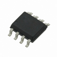
CS4334-DSZ Cirrus Logic Inc, CS4334-DSZ Datasheet - Page 3

CS4334-DSZ
Manufacturer Part Number
CS4334-DSZ
Description
IC DAC STER 24BIT 96KHZ 8-SOIC
Manufacturer
Cirrus Logic Inc
Datasheet
1.CS4334-KSZ.pdf
(24 pages)
Specifications of CS4334-DSZ
Data Interface
Serial
Number Of Bits
24
Number Of Converters
2
Voltage Supply Source
Single Supply
Power Dissipation (max)
104mW
Operating Temperature
-40°C ~ 85°C
Mounting Type
Surface Mount
Package / Case
8-SOIC
Resolution (bits)
24bit
Sampling Rate
96kSPS
Input Channel Type
Serial
Supply Voltage Range - Analog
4.75V To 5.5V
Supply Current
15mA
Digital Ic Case Style
SOIC
Package
8SOIC
Resolution
24 Bit
Conversion Rate
96 KSPS
Architecture
Delta-Sigma
Digital Interface Type
Serial
Number Of Outputs Per Chip
2
Output Type
Voltage
Full Scale Error
±5(Typ) %FSR
Lead Free Status / RoHS Status
Lead free / RoHS Compliant
For Use With
598-1510 - BOARD EVAL FOR CS4334 CODEC
Settling Time
-
Lead Free Status / RoHS Status
Lead free / RoHS Compliant, Lead free / RoHS Compliant
Other names
598-1631
Available stocks
Company
Part Number
Manufacturer
Quantity
Price
Company:
Part Number:
CS4334-DSZ
Manufacturer:
CIRRUS
Quantity:
275
Company:
Part Number:
CS4334-DSZ
Manufacturer:
TI
Quantity:
6 224
Part Number:
CS4334-DSZ
Manufacturer:
CIRRUS
Quantity:
20 000
DS248F5
LIST OF TABLES
PIN DESCRIPTIONS
No.
1
2
3
4
5
6
7
8
DE-EMPHASIS / SCLK
LEFT / RIGHT CLOCK
SERIAL DATA INPUT
Pin Name
DEM/SCLK
Figure 18. Passband Ripple...................................................................................................................... 18
Figure 19. Stopband Rejection.................................................................................................................. 19
Figure 20. Transition Band........................................................................................................................ 19
Figure 21. Transition Band........................................................................................................................ 19
Figure 22. Passband Ripple...................................................................................................................... 19
Figure 23. 0 dBFS FFT (BRM) .................................................................................................................. 20
Figure 24. -60 dBFS FFT (BRM).............................................................................................................. 20
Figure 25. Idle Channel Noise FFT (BRM)................................................................................................ 20
Figure 26. Twin Tone IMD FFT (BRM)...................................................................................................... 20
Figure 27. THD+N vs. Amplitude (BRM) ................................................................................................... 20
Figure 28. THD+N vs. Frequency (BRM) .................................................................................................. 20
Figure 29. 0 dBFS FFT (HRM).................................................................................................................. 21
Figure 30. -60 dBFS FFT (HRM).............................................................................................................. 21
Figure 31. Idle Channel Noise FFT (HRM) ............................................................................................... 21
Figure 32. Twin Tone IMD FFT (HRM) ..................................................................................................... 21
Figure 33. THD+N vs. Amplitude (HRM)................................................................................................... 21
Figure 34. THD+N vs. Frequency (HRM)................................................................................................. 21
Table 1. Common Clock Frequencies ...................................................................................................... 13
AOUTR
AOUTL
SDATA
AGND
MCLK
LRCK
MASTER CLOCK
VA
I/O
O Analog Right Channel Output - Typically 3.5 Vp-p for a full-scale input signal.
O Analog Left Channel Output - Typically 3.5 Vp-p for a full-scale input signal.
I
I
I
I
I
I
Serial Audio Data Input - Two’s complement MSB-first serial data is input on this pin. The data is
clocked into the CS4334/5/8/9 via internal or external SCLK, and the channel is determined by
LRCK.
De-Emphasis/External Serial Clock Input - Used for de-emphasis filter control or external serial
clock input.
Left/Right Clock - Determines which channel is currently being input on the Audio Serial Data
Input pin, SDATA.
Master Clock - Frequency must be 256x, 384x, or 512x the input sample rate in BRM and either
128x or 192x the input sample rate in HRM.
Analog Ground - Analog ground reference is 0V.
Analog Power - Analog power supply is nominally +5 V.
DEM/SCLK
SDATA
MCLK
LRCK
Confidential Draft
1
2
3
4
Pin Function and Description
3/11/08
8
7
6
5
AOUTL
VA
AGND
AOUTR
ANALOG LEFT CHANNEL OUTPUT
ANALOG POWER
ANALOG GROUND
ANALOG RIGHT CHANNEL OUTPUT
CS4334/5/8/9
3


