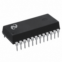
DAC1210LCJ National Semiconductor, DAC1210LCJ Datasheet - Page 8

DAC1210LCJ
Manufacturer Part Number
DAC1210LCJ
Description
IC DAC 12BIT MPU 24-DIP
Manufacturer
National Semiconductor
Series
MICRO-DAC™r
Datasheet
1.DAC1210LCJ.pdf
(18 pages)
Specifications of DAC1210LCJ
Settling Time
1µs
Number Of Bits
12
Data Interface
Parallel
Number Of Converters
1
Voltage Supply Source
Single Supply
Power Dissipation (max)
500mW
Operating Temperature
-40°C ~ 85°C
Mounting Type
Through Hole
Package / Case
*
Case
DIP-24L
Lead Free Status / RoHS Status
Contains lead / RoHS non-compliant
Other names
*DAC1210LCJ
Available stocks
Company
Part Number
Manufacturer
Quantity
Price
Company:
Part Number:
DAC1210LCJ
Manufacturer:
NS
Quantity:
960
Company:
Part Number:
DAC1210LCJ
Manufacturer:
NS
Quantity:
960
Part Number:
DAC1210LCJ
Manufacturer:
NS/国半
Quantity:
20 000
Company:
Part Number:
DAC1210LCJ-1
Manufacturer:
NS
Quantity:
2 067
Application Hints
1 4 Left-Justified Data Format
It is important to realize that the input registers of these
DACs are arranged to accept a left-justified data word from
the microprocessor with the most significant 8 bits coming
first (Byte 1) and the lower 4 bits second Left justification
simply means that the binary point is assumed to be located
to the left of the most significant bit Figure 3 shows how the
12 bits of DAC data should be arranged in 2 8-bit registers
of an 8-bit processor before being written to the DAC
FIGURE 3 Left-Justified Data Format
X
e
don’t care
(Continued)
FIGURE 4 16-Bit Data Bus Interface for the DAC1208 Series
XFER and WR2 grounded Byte 1 Byte 2 tied to V
TL H 5690-10
Interface Timing
8
1 5 16-Bit Data Bus Interface
The DAC1208 series provides all 12 digital input lines to
permit a direct parallel interface to a 16-bit data bus In this
instance double buffering is not always necessary (unless a
simultaneous updating of several DACs or a data transfer
via an external strobe is desired) so the 12-bit DAC register
can be wired to flow-through whereby its Q outputs always
reflect the state of its D inputs The external connections
required and the timing diagram for this single buffered ap-
plication are shown in Figure 4 Note that either left or right-
justified data from the processor can be accommodated
with a 16-bit data bus
1 6 Flow-Through Operation
Through primarily designed to provide microprocessor inter-
face compatibility the MICRO-DACs can easily be config-
ured to allow the analog output to continuously reflect the
state of an applied digital input This is most useful in appli-
CC
TL H 5690-11


