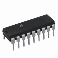
DAC1218LCJ National Semiconductor, DAC1218LCJ Datasheet - Page 3

DAC1218LCJ
Manufacturer Part Number
DAC1218LCJ
Description
IC DAC 12BIT 18-DIP
Manufacturer
National Semiconductor
Datasheet
1.DAC1218LCJ.pdf
(12 pages)
Specifications of DAC1218LCJ
Settling Time
1µs
Number Of Bits
12
Number Of Converters
1
Voltage Supply Source
Single Supply
Power Dissipation (max)
500mW
Operating Temperature
-40°C ~ 85°C
Mounting Type
Through Hole
Package / Case
*
Case
DIP-18L
Lead Free Status / RoHS Status
Contains lead / RoHS non-compliant
Data Interface
-
Other names
*DAC1218LCJ
Available stocks
Company
Part Number
Manufacturer
Quantity
Price
Company:
Part Number:
DAC1218LCJ
Manufacturer:
SIPEX
Quantity:
281
Part Number:
DAC1218LCJ
Manufacturer:
NS/国半
Quantity:
20 000
Company:
Part Number:
DAC1218LCJ-1
Manufacturer:
ON
Quantity:
19
Company:
Part Number:
DAC1218LCJ-1
Manufacturer:
MOT
Quantity:
2
Electrical Characteristics Notes
Note 1 Absolute Maximum Ratings indicate limits beyond which damage to the device may occur DC and AC electrical specifications do not apply when operating
the device beyond its specified operating conditions
Note 2 All voltages are measured with respect to GND unless otherwise specified
Note 3 This 500 mW specification applies for all packages The low intrinsic power dissipation of this part (and the fact that there is no way to significantly modify
the power dissipation) removes concern for heat sinking
Note 4 Both I
example if V
Note 5 The unit FSR stands for full-scale range Linearity Error and Power Supply Rejection specs are based on this unit to eliminate dependence on a particular
V
zero and full-scale adjustment the plot of the 4096 analog voltage outputs will each be within 0 012%
scale The unit ppm of FSR (parts per million of full-scale range) and ppm of FS (parts per million of full-scale) are used for convenience to define specs of very
small percentage values typical of higher accuracy converters 1 ppm of FSR
example the gain error tempco spec of
g
Note 6 To achieve this low feedthrough in the D package the user must ground the metal lid If the lid is left floating the feedthrough is typically 6 mV
Note 7 A 10 nA leakage current with R
Note 8 Human body model 100 pF discharged through 1 5 k
Note 9 Tested limit for
Note 10 Typicals are at 25 C and represent the most likely parametric norm
Note 11 Tested limits are guaranteed to National’s AOQL (Average Outgoing Quality Level)
Note 12 Design limits are guaranteed but not 100% production tested These limits are not used to calculate outgoing quality levels
Typical Performance Characteristics
REF
(6)(V
value to indicate the true performance of the part The Linearity Error specification of the DAC1218 is 0 012% of FSR This guarantees that after performing a
REF
10
REF
OUT1
6
)(125 C) or
e
10V then a 1 mV offset V
and I
b
Digital Input Threshold
vs V
Gain and Linearity Error
Variation vs Temperature
OUT2
1 suffix parts applies only at 25 C
g
0 75 (10
CC
must go to ground or the virtual ground of an operational amplifier The linearity error is degraded by approximately V
b
3
Fb
) V
g
e
REF
6 ppm of FS C represents a worst-case full-scale gain error change with temperature from
20k and V
OS
which is
on I
OUT1
REF
g
e
0 075% of V
or I
10V corresponds to a zero error of (10
OUT2
resistor
will introduce an additional 0 01% linearity error
REF
e
V
3
REF
10
6
is the conversion factor to provide an actual output voltage quantity For
c
c
10
V
b
REF
9 c
of a straight line which passes through zero and full-
20
Digital Input Threshold
vs Temperature
Gain and Linearity Error
Variation vs Supply Voltage
c
10
3
)
c
100% 10V or 0 002% of FS
b
40 C to
OS
TL H 5691– 2
d
V
a
REF
85 C of
For


