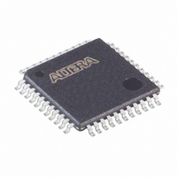
EPM7064STC44-7N Altera, EPM7064STC44-7N Datasheet - Page 39

EPM7064STC44-7N
Manufacturer Part Number
EPM7064STC44-7N
Description
IC MAX 7000 CPLD 64 44-TQFP
Manufacturer
Altera
Series
MAX® 7000r
Datasheet
1.EPM7064STC44-10.pdf
(66 pages)
Specifications of EPM7064STC44-7N
Programmable Type
In System Programmable
Delay Time Tpd(1) Max
7.5ns
Voltage Supply - Internal
4.75 V ~ 5.25 V
Number Of Logic Elements/blocks
4
Number Of Macrocells
64
Number Of Gates
1250
Number Of I /o
36
Operating Temperature
0°C ~ 70°C
Mounting Type
Surface Mount
Package / Case
44-TQFP, 44-VQFP
Voltage
5V
Memory Type
EEPROM
Number Of Logic Elements/cells
4
Family Name
MAX 7000S
# Macrocells
64
Number Of Usable Gates
1250
Frequency (max)
166.7MHz
Propagation Delay Time
7.5ns
Number Of Logic Blocks/elements
4
# I/os (max)
36
Operating Supply Voltage (typ)
5V
In System Programmable
Yes
Operating Supply Voltage (min)
4.75V
Operating Supply Voltage (max)
5.25V
Operating Temp Range
0C to 70C
Operating Temperature Classification
Commercial
Mounting
Surface Mount
Pin Count
44
Package Type
TQFP
Lead Free Status / RoHS Status
Lead free / RoHS Compliant
Features
-
Lead Free Status / Rohs Status
Compliant
Other names
544-2022
EPM7064STC44-7N
EPM7064STC44-7N
Available stocks
Company
Part Number
Manufacturer
Quantity
Price
Company:
Part Number:
EPM7064STC44-7N
Manufacturer:
ALTERA
Quantity:
8 831
Part Number:
EPM7064STC44-7N
Manufacturer:
ALTERA/阿尔特拉
Quantity:
20 000
Notes to tables:
(1)
(2)
(3)
(4)
(5)
(6)
(7)
(8)
Altera Corporation
Symbol
t
t
t
t
t
t
t
t
t
t
t
t
t
t
t
t
t
f
t
PD1
PD2
SU
H
FSU
FH
CO1
CH
CL
ASU
AH
ACO1
ACH
ACL
CPPW
ODH
CNT
CNT
ACNT
Table 27. EPM7032S External Timing Parameters (Part 1 of 2)
These values are specified under the recommended operating conditions shown in
information on switching waveforms.
This parameter applies to MAX 7000E devices only.
This minimum pulse width for preset and clear applies for both global clear and array controls. The t
must be added to this minimum width if the clear or reset signal incorporates the t
path.
This parameter is a guideline that is sample-tested only and is based on extensive device characterization. This
parameter applies for both global and array clocking.
These parameters are measured with a 16-bit loadable, enabled, up/down counter programmed into each LAB.
The f
Operating conditions: V
The t
running in the low-power mode.
LPA
MAX
Input to non-registered output
I/O input to non-registered
output
Global clock setup time
Global clock hold time
Global clock setup time of fast
input
Global clock hold time of fast
input
Global clock to output delay
Global clock high time
Global clock low time
Array clock setup time
Array clock hold time
Array clock to output delay
Array clock high time
Array clock low time
Minimum pulse width for clear
and preset
Output data hold time after
clock
Minimum global clock period
Maximum internal global clock
frequency
Minimum array clock period
parameter must be added to the t
values represent the highest frequency for pipelined data.
Parameter
CCIO
= 3.3 V ± 10% for commercial and industrial use.
Tables 27
C1 = 35 pF
C1 = 35 pF
C1 = 35 pF
C1 = 35 pF
(2)
C1 = 35 pF
(4)
Conditions
LAD
and
, t
(3)
LAC
MAX 7000 Programmable Logic Device Family Data Sheet
28
175.4
, t
Min Max Min Max Min Max Min Max
2.9
0.0
2.5
0.0
2.0
2.0
0.7
1.8
2.5
2.5
2.5
1.0
show the EPM7032S AC operating conditions.
IC
, t
-5
EN
5.0
5.0
3.2
5.4
5.7
5.7
, t
SEXP
142.9
, t
4.0
0.0
2.5
0.0
2.5
2.5
0.9
2.1
2.5
2.5
2.5
1.0
ACL
Note (1)
-6
Speed Grade
, and t
6.0
6.0
3.5
6.6
7.0
7.0
CPPW
116.3
5.0
2.5
0.0
3.0
1.1
2.7
3.0
3.0
3.0
1.0
0.0
3.0
Table
LAD
parameters for macrocells
-7
parameter into the signal
7.5
7.5
4.3
8.2
8.6
8.6
14. See
100.0
7.0
0.0
3.0
0.5
4.0
4.0
2.0
3.0
4.0
4.0
4.0
1.0
Figure 13
-10
LPA
10.0
10.0
10.0
10.0
10.0
5.0
parameter
for more
Unit
MHz
ns
ns
ns
ns
ns
ns
ns
ns
ns
ns
ns
ns
ns
ns
ns
ns
ns
ns
39


