LVR5 .035 1%TR Vishay, LVR5 .035 1%TR Datasheet - Page 2
LVR5 .035 1%TR
Manufacturer Part Number
LVR5 .035 1%TR
Description
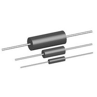
Current Sense Resistors - Through Hole .035ohms 1% 5watts
Manufacturer
Vishay
Series
LVR5r
Datasheet
1.LVR03R060FB12.pdf
(3 pages)
Specifications of LVR5 .035 1%TR
Resistance
0.035 Ohms
Power Rating
5 Watts
Tolerance
1 %
Operating Temperature Range
- 65 C to + 175 C
Dimensions
8.38 mm Dia. x 23.5 mm L
Termination Style
Axial
Lead Free Status / Rohs Status
Lead free / RoHS Compliant


LVR
Vishay Dale
DIMENSIONS in inches [millimeters]
Note
(1)
MATERIAL SPECIFICATIONS
Element: Self-supporting nickel-chrome alloy
(LVR10 also utilizes manganin)
Encapsulation: High temperature mold compound
Terminals: Tinned copper
Part Marking: Dale, model, wattage, value, tolerance, date
code
Packaging: Reference “Wirewound Through Hole Resistor
Packaging” (www.vishay.com/doc?21028)
The improved TCR characteristics of these LVR models
from - 55 °C to + 125 °C (reference to + 25 °C) are as follows:
TCR vs. RESISTANCE VALUE
www.vishay.com
2
PERFORMANCE
TEST
Thermal Shock
Short Time Overload
Low Temperature Storage
High Temperature Exposure
Dielectric Withstanding Voltage
Insulation Resistance
Moisture Resistance
Shock, Specified Pulse
Vibration, High Frequency
Load Life
Bias Humidity
On some standard reel pack methods, the leads may be trimmed to a shorter length than shown
400
300
200
100
0.02
B
Wirewound Resistors, Precision Power, Low Value, Commercial,
0.04
LVR05
LVR03
A
0.06
- 65 °C to + 125 °C, 5 cycles, 15 min at each extreme
5 x rated power (LVR01, 03, 05), 10 x rated power (LVR10) for 5 s
- 65 °C for 24 h
250 h at + 275 °C (+ 175 °C for LVR01)
1000 V
MIL-STD-202 Method 302, 100 V
MIL-STD-202 Method 106, 7b not applicable
MIL-STD-202 Method 213, 100 g's for 6 ms, 10 shocks
Frequency varied 10 Hz to 2000 Hz, 20 g peak, 2 directions 6 h each
2000 h at rated power, + 25 °C, 1.5 h “ON”, 0.5 h “OFF”
+ 85 °C, 85 % RH, 10 % bias, 1000 h
LVR10
For technical questions, contact:
1.50 [38.10]
RMS
0.08
minimum
LVR01
, 1 min
C
RESISTANCE (Ω)
(1)
0.10
CONDITIONS OF TEST
Axial Lead
ww2aresistors@vishay.com
SURFACE TEMPERATURE vs. POWER
DERATING
MODEL
LVR01
LVR03
LVR05
LVR10
120
100
80
60
40
20
- 65
0
250
200
150
100
50
LVR01
- 25
± 0.010 [0.254]
1
0.427 [10.85]
0.560 [14.22]
0.925 [23.50]
1.828 [46.43]
2
25
A
DIMENSIONS in inches [millimeters]
LVR03
3
75
4
LVR01
± 0.010 [0.254]
0.115 [2.92]
0.205 [5.21]
0.330 [8.38]
0.392 [9.96]
LVR05
5
AMBIENT TEMPERATURE IN °C
125
B
± (0.2 % + 0.0005 ) R
± (0.5 % + 0.0005 ) R
± (0.2 % + 0.0005 ) R
± (2.0 % + 0.0005 ) R
± (0.1 % + 0.0005 ) R
± (0.2 % + 0.0005 ) R
± (0.1 % + 0.0005 ) R
± (0.1 % + 0.0005 ) R
± (2.0 % + 0.0005 ) R
± (1.0 % + 0.0005 ) R
Document Number: 30206
6
1000 M minimum
TEST LIMITS
Revision: 21-Feb-11
175
LVR03
LVR05
LVR10
7
± 0.002 [0.051]
0.020 [0.508]
0.032 [0.813]
0.040 [1.02]
0.040 [1.02]
8
LVR10
POWER IN W
225
C
9
275
10
Related parts for LVR5 .035 1%TR
Image
Part Number
Description
Manufacturer
Datasheet
Request
R

Part Number:
Description:
357-036-542-201 CARDEDGE 36POS DL .156 BLK LOPRO
Manufacturer:
Vishay
Datasheet:
Part Number:
Description:
357-036-542-201 CARDEDGE 36POS DL .156 BLK LOPRO
Manufacturer:
Vishay
Datasheet:
Part Number:
Description:
357-036-542-201 CARDEDGE 36POS DL .156 BLK LOPRO
Manufacturer:
Vishay
Datasheet:
Part Number:
Description:
357-036-542-201 CARDEDGE 36POS DL .156 BLK LOPRO
Manufacturer:
Vishay
Datasheet:
Part Number:
Description:
357-036-542-201 CARDEDGE 36POS DL .156 BLK LOPRO
Manufacturer:
Vishay
Datasheet:
Part Number:
Description:
357-036-542-201 CARDEDGE 36POS DL .156 BLK LOPRO
Manufacturer:
Vishay
Datasheet:
Part Number:
Description:
357-036-542-201 CARDEDGE 36POS DL .156 BLK LOPRO
Manufacturer:
Vishay
Datasheet:
Part Number:
Description:
357-036-542-201 CARDEDGE 36POS DL .156 BLK LOPRO
Manufacturer:
Vishay
Datasheet:
Part Number:
Description:
357-036-542-201 CARDEDGE 36POS DL .156 BLK LOPRO
Manufacturer:
Vishay
Datasheet:
Part Number:
Description:
357-036-542-201 CARDEDGE 36POS DL .156 BLK LOPRO
Manufacturer:
Vishay
Datasheet:
Part Number:
Description:
357-036-542-201 CARDEDGE 36POS DL .156 BLK LOPRO
Manufacturer:
Vishay
Datasheet:
Part Number:
Description:
357-036-542-201 CARDEDGE 36POS DL .156 BLK LOPRO
Manufacturer:
Vishay
Datasheet:
Part Number:
Description:
357-036-542-201 CARDEDGE 36POS DL .156 BLK LOPRO
Manufacturer:
Vishay
Datasheet:
Part Number:
Description:
357-036-542-201 CARDEDGE 36POS DL .156 BLK LOPRO
Manufacturer:
Vishay
Datasheet:
Part Number:
Description:
357-036-542-201 CARDEDGE 36POS DL .156 BLK LOPRO
Manufacturer:
Vishay
Datasheet: