ULR3R001FLFTR IRC, ULR3R001FLFTR Datasheet
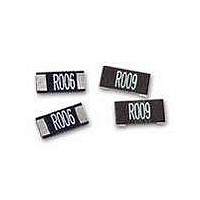
Current Sense Resistors - SMD 3W 0.001 OHM 1%

ULR3R001FLFTR

Manufacturer Part Number
ULR3R001FLFTR
Description
Current Sense Resistors - SMD 3W 0.001 OHM 1%
Manufacturer
IRC
Series
ULRr
Datasheet

Specifications of ULR3R001FLFTR

Resistance
0.001 Ohms
Power Rating
3 Watts
Tolerance
1 %
Temperature Coefficient
+/- 50 PPM / C
Package / Case
2512 (6332 metric)
Product
Metal Element Current Sensing Resistors
Operating Temperature Range
- 55 C to + 170 C
Dimensions
3.2 mm W x 6.3 mm L x 0.6 mm H
Termination Style
SMD/SMT
Lead Free Status / Rohs Status
Lead free / RoHS Compliant
ULR
Metal Element
Current Sense Resistor
Notes:
1 Non-standard resistance values available (contact factory). For resistance values above 20 mΩ, please refer to our LRC / LRF / LRMA series. 2 Black
coating = wave or IR re ow soldering; Green coating = IR re ow solder. Wave re ow - solder mask must match the W and D dimensions on page 2 of data
sheet. 3 Package sizes 2010 and 1206 with the green coating are uncoated on the top surface and unmarked for resistance value.
General Note
IRC reserves the right to make changes in product speci cation without notice or liability.
All information is subject to IRC’s own data and is considered accurate at time of going to print.
Wire and Film Technologies Division
Telephone: 361 992 7900 • Facsimile: 361 992 3377 • Website: www.irctt.com
Environmental Data
Electrical Data
1206 Chip Size
ULRG1
2010 Chip Size
ULRG15
2512 Chip Size
ULRG1
U
U
U
ULRB1
U
Test
Short Term Overload (5x rated power for 5 seconds)
Load at rated power (1000 hours cyclic load @ 70°C)
Temperatature Cycling (-55°C to +150°C; 1000 cycles)
Dry Heat (+170°C, no load; 1000 hours)
Resistance to Solder Heat (260°C for 10 seconds)
S
R
O
IRC Type
o
L
L
L
L
e
p
R
R
R
R
d l
s
r e
s i
Robust metal strip able to withstand high temperature and high current.
Low TCR and Inductance
Resistance Range from 0.5 mΩ to 15 mΩ
Power ratings from 1W to 3W in 1206, 2010 and 2512 chip size
Designed for current sense circuits in power electronic systems
Higher wattage devices feature PCB clearance gap to maximize thermal
performance
B
G
G
G
e
t a
a t
a r
2
2
2
3
n i
5
n
l i b
c
g
e
y t i
T
e
o t
Coating
2 (
m
Green
Green
Green
S
Black
p
3
o
e
° 5
v l
a r
C
e
u t
n
f
2
r o
s t
e r
2
at 80°C (Watts)
Power rating
s
e
c
o
n
1.5
2
1
1
2
3
1
2
d
5 .
) s
1, 2, 3, 5, 7, 10
1, 2, 3, 5, 7, 10
1
, 7
, 4
. 0
1, 1.5, 2, 2.5, 3
. 2
, 4
, 6
. 0
• 4222 South Staples Street • Corpus Christi Texas 78411 USA
, 1
, 5
, 5
, 5
, 8
. 4
5
7
Standard Resistance
1
, 5
0
3
0
, 2
, 9
7 .
7 .
Values (mΩ)
, 5
1
1
5
, 5
5
0
6
, 1
. 1
, 5
2
∆R/R ≤ ± 0.5% + 0.5 mΩ (black); ∆R/R ≤ ± 1% (green)
∆R/R ≤ ± 1% + 0.5 mΩ (black); ∆R/R ≤ ± 1% (green)
∆R/R ≤ ± 0.5% + 0.5 mΩ (black); ∆R/R ≤ ± 1% (green)
∆R/R ≤ ± 1% + 0.5 mΩ (black); ∆R/R ≤ ± 1% (green)
∆R/R ≤ ± 0.5% + 0.5 mΩ (black); ∆R/R ≤ ± 1% (green)
M
N
5 -
1
o
i n i
° 5
d
m
C
e
u
e t
o t
m
i r
1
r o
9
7
5
t a
(±ppm/°C)
° 0
%
o i
C
TCR
n
1
1
1
c
50
50
5
5
5
50
7
5
o
0
5
0
f o
0
0
0
5
0
v
0
0
0
e
p
a r
o r
g
e t
e
Tolerance
c
v i t
(±%)
1, 5
1, 5
1, 5
e
c
o
t a
n i
ULR Issue April 2011 Sheet 1 of 6
g
Withstanding Voltage
r o
m
a
Dielectric
k r
(Volts)
n i
100
100
200
g
TT electronics plc
A Subsidiary of

Related parts for ULR3R001FLFTR

ULR3R001FLFTR Summary of contents

Page 1

... General Note IRC reserves the right to make changes in product speci cation without notice or liability. All information is subject to IRC’s own data and is considered accurate at time of going to print. Wire and Film Technologies Division Telephone: 361 992 7900 • Facsimile: 361 992 3377 • Website: www.irctt.com ...

Page 2

... Note: 1 Dimensions are for reference only. All units are displayed in mm. Wire and Film Technologies Division Telephone: 361 992 7900 • Facsimile: 361 992 3377 • Website: www.irctt.com 3.20±0.25 1.60±0.10 5.08±0.25 2.54±0.15 6.35 ± 0.25 3.00 ± ...

Page 3

... Black All 1.85 0.5 2.78 0.75 2. 1.5 2. 1.28 2512 - Green 4 2. 2. 1.28 Note: Nominal values; tolerances not included Wire and Film Technologies Division Telephone: 361 992 7900 • Facsimile: 361 992 3377 • Website: www.irctt.com 2 2-wire pad layout ...

Page 4

... Pocket position relative to sprocket hole is measured as the true position of the pocket and not the pocket hole. Wire and Film Technologies Division Telephone: 361 992 7900 • Facsimile: 361 992 3377 • Website: www.irctt.com Green Type A low TCR alloy plate is grooved to set the nal resistance. ...

Page 5

... Tolerance: The device manufacturer/supplier shall assure process compat- ibility up to and including the stated classi cation temperature at the rated MSL level. Wire and Film Technologies Division Telephone: 361 992 7900 • Facsimile: 361 992 3377 • Website: www.irctt.com Sn-Pb Eutectic and Pb-Free Reflow Profiles Ramp-up smax ...

Page 6

... R002 = 2 mΩ; R designates the decimal location in ohms. • 4-digit: 1M50 = 1.5 mΩ; M designates the decimal location in milli-ohm. • 3-digit: 1M5 = 1.5 mΩ; M designates the decimal location in milli-ohm. Wire and Film Technologies Division Telephone: 361 992 7900 • Facsimile: 361 992 3377 • Website: www.irctt.com 1 2512 R010 F LF • ...

Related keywords