CAY17-433JBLF Bourns Inc., CAY17-433JBLF Datasheet
CAY17-433JBLF
Manufacturer Part Number
CAY17-433JBLF
Description
Resistor Networks & Arrays 43K 5% 10pin Dual Ground 1/6
Manufacturer
Bourns Inc.
Series
CAY17r
Datasheet
1.CAY17-103JALF.pdf
(2 pages)
Specifications of CAY17-433JBLF
Product Type
Arrays
Circuit Type
Bussed
Number Of Resistors
8
Resistance
43 KOhms
Tolerance
5 %
Temperature Coefficient
+/- 250 PPM / C
Number Of Pins
10
Package / Case
1206 (3216 metric)
Operating Temperature Range
- 55 C to + 125 C
Termination Style
SMD/SMT
Lead Free Status / Rohs Status
Lead free / RoHS Compliant


Protective
Glass Overcoat
Number of Resistors .. 8 (bussed circuit)
Power Rating per Resistor @ 70 °C
Package Power Rating @ 70 °C
Operating Temperature Range
Derated to 0 Load @ ..................+125 °C
Max. Working Voltage ......................25 V
Max. Overload Voltage ....................50 V
Resistance Tolerance .................... ±5 %
Resistance Range/E24 Series
T.C.R. ................................ ±250 ppm/°C
Chip Arrays
Type
• Y = Convex
Model
• 17 = 1206 Package Size
Resistance Code
• 103 = 10K ohms
Resistance Tolerance
• J = ±5 %
Resistors
• A = Common from terminal 5 to 10
• B = Common from terminal 1 to 6
Terminations
• LF = Tin-plated (RoHS compliant)
For Standard Values Used in Capacitors,
Inductors, and Resistors,
How To Order
Characteristics
JA version ..... 10 ohms to 100K ohms
JB version ....... 10 ohms to 43K ohms
Construction
(JA range: 10 ohms to 100K ohms;
JB range: 10 ohms to 43K ohms)
................................................ 31 mW
.............................................. 250 mW
............................... -55 °C to +155 °C
Termination
CA Y 17 - 103 J A LF
click
Thick Film
Resistive Element
here.
High Purity
Alumina
Substrate
Features
■
■
■
■
■
■
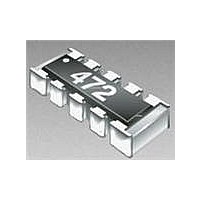
Model CAY17 - Bussed Resistor Array
Product Dimensions
Derating Curve
Packaging Dimensions
JA version available to 100K ohms
10 pin with 8 resistors in bussed type for
pull up/down circuit
RoHS compliant*
Convex termination style
Resistance tolerance ±5 %
E24 Series from 10 ohms to 43K ohms
100
80
60
40
20
0
(.039)
(.055)
(.012 ± .008)
-55
1.0
1.4
0.3 ± 0.2
Ambient Temp. (˚C)
MAX.
MAX.
(.025)
0.64
40
(.079 ± .020)
60
2.0 ± 0.5
70 °C
(.142 ± .008)
(.059 + .004 - 0)
3.6 ± 0.2
80 100 120 140 160
1.5 + 0.1 - 0
(7.087)
Customers should verify actual device performance in their specifi c applications
180
R 1 0 2
125 °C
DIMENSIONS:
(.126 ± .008)
3.2 ± 0.2
(.079 ± .008)
2.0 ± 0.2
(.827 ± .031)
21.0 ± 0.8
(.511 ± .008)
(.158 ± .004)
13.0 ± 0.2
*RoHS Directive 2002/95/EC Jan 27, 2003 including Annex.
4.0 ± 0.1
(INCHES)
■
■
MM
Suitable for all types of soldering processes
Paper tape on plastic reel for automatic
placement
Bussed Circuits - Option A
Specifi cations are subject to change without notice.
(.063 ± .008)
(.013 ± .006)
10
1.6 ± 0.2
0.34 ± 0.15
1
(.022 ± .004)
(.354 ± .012)
0.55 ± 0.1
(2.362)
9.0 ± 0.3
R
60
2
9
(.157 ± .004)
(.449 ± .040)
R
R
4.0 ± 0.1
11.4 ± 1.0
3
8
(.138 ± .002)
3.5 ± 0.05
R
R
4
7
(.315 ± .008)
(.020 ± .004)
R
R
(.008 ± .006)
8.0 ± 0.2
0.5 ± 0.1
0.2 ± 0.15
6
5
R
Related parts for CAY17-433JBLF
Image
Part Number
Description
Manufacturer
Datasheet
Request
R

Part Number:
Description:
Resistor Network,Thick Film,43KOhms,25WV,5+/-% Tol,-250,250ppm-TC,1206-Case
Manufacturer:
Bourns Inc.
Datasheet:
Part Number:
Description:
Resistor Networks & Arrays 43Kohms 5% 10pin Dual Ground 1/6
Manufacturer:
Bourns Inc.
Datasheet:
Part Number:
Description:
Resistor Networks & Arrays 43Kohms 5% 10pin Dual Ground 5/10
Manufacturer:
Bourns Inc.
Datasheet:
Part Number:
Description:
RESISTOR, BUS ARRAY 8RES 4.7KOHM 5% 1206
Manufacturer:
Bourns Inc.
Datasheet:
Part Number:
Description:
Resistor Networks & Arrays 4.7Kohms 5% 10pin Dual Ground 5/10
Manufacturer:
Bourns Inc.
Datasheet:

Part Number:
Description:
Resistor Network,Thick Film,100KOhms,25WV,5+/-% Tol,-250,250ppm-TC,1206-Case
Manufacturer:
Bourns Inc.
Datasheet:
Part Number:
Description:
Resistor Networks & Arrays 10K 5% 10pin Dual Ground 5/8
Manufacturer:
Bourns Inc.
Datasheet:
Part Number:
Description:
RESISTOR, BUS RES ARRAY 8, 1KOHM 5%, 1206
Manufacturer:
Bourns Inc.
Datasheet:
Part Number:
Description:
Resistor Network,Thick Film,150Ohms,25WV,5+/-% Tol,-250,250ppm-TC,1206-Case
Manufacturer:
Bourns Inc.
Datasheet:
Part Number:
Description:
Resistor Network,Thick Film,1.5KOhms,25WV,5+/-% Tol,-250,250ppm-TC,1206-Case
Manufacturer:
Bourns Inc.
Datasheet:

Part Number:
Description:
Manufacturer:
Bourns, Inc.
Datasheet:
Part Number:
Description:
11mm Potentiometer
Manufacturer:
Bourns, Inc.
Datasheet:
CAY17-433JBLF Summary of contents
Page 1
... RoHS compliant* ■ Convex termination style ■ Resistance tolerance ±5 % ■ E24 Series from 10 ohms to 43K ohms Model CAY17 - Bussed Resistor Array Product Dimensions 0.3 ± 0.2 (.012 ± .008 0.64 (.025) 3.2 ± 0.2 (.126 ± .008) Derating Curve 70 ° ...
Page 2
... Model CAY17 - Bussed Resistor Array Soldering Profi le for RoHS Compliant Chip Resistors and Arrays 275 <1> Maximum of 20 seconds between +255 °C and +260 °C 225 175 150 °C 125 REV. 03/11 Specifi cations are subject to change without notice. ...