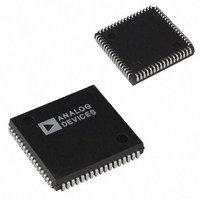
ADSP-2101BPZ-100 Analog Devices Inc, ADSP-2101BPZ-100 Datasheet - Page 34

ADSP-2101BPZ-100
Manufacturer Part Number
ADSP-2101BPZ-100
Description
IC DSP SLG 16BIT 25MHZ 68-PLCC
Manufacturer
Analog Devices Inc
Series
ADSP-21xxr
Type
Fixed Pointr
Datasheet
1.ADSP-2115BPZ-100.pdf
(64 pages)
Specifications of ADSP-2101BPZ-100
Interface
Synchronous Serial Port (SSP)
Clock Rate
25MHz
Non-volatile Memory
External
On-chip Ram
6kB
Voltage - I/o
5.00V
Voltage - Core
5.00V
Operating Temperature
-40°C ~ 85°C
Mounting Type
Surface Mount
Package / Case
68-PLCC
No. Of Bits
16
Frequency
25MHz
Core Supply Voltage
5.5V
No. Of Mips
25
Supply Voltage Range
4.5V To 5.5V
Operating Temperature Range
-40°C To +85°C
Digital Ic Case Style
PLCC
Embedded Interface Type
Host Port
Rohs Compliant
Yes
Lead Free Status / RoHS Status
Lead free / RoHS Compliant
Available stocks
Company
Part Number
Manufacturer
Quantity
Price
Company:
Part Number:
ADSP-2101BPZ-100
Manufacturer:
Analog Devices Inc
Quantity:
10 000
ADSP-21xx
TIMING PARAMETERS (ADSP-2101/2105/2111/2115/2161/2163)
MEMORY WRITE
Parameter
Switching Characteristic:
t
t
t
t
t
t
t
t
t
t
Parameter
Switching Characteristic:
t
t
t
t
t
t
t
t
t
t
NOTES
1
w = wait states
DW
DH
WP
WDE
ASW
DDR
CWR
AW
WRA
WWR
For 25 MHz only the minimum frequency dependency formula for t
DW
DH
WP
WDE
ASW
DDR
CWR
AW
WRA
WWR
Data Setup before WR High
Data Hold after WR High
WR Pulse Width
WR Low to Data Enabled
A0–A13, DMS, PMS Setup before WR Low
Data Disable before WR or RD Low
CLKOUT High to WR Low
A0–A13, DMS, PMS, Setup before WR
Deasserted
A0–A13, DMS, PMS Hold after WR
Deasserted
WR High to RD or WR Low
Data Setup before WR High
Data Hold after WR High
WR Pulse Width
WR Low to Data Enabled
A0–A13, DMS, PMS Setup before
WR Low
Data Disable before WR or RD Low
CLKOUT High to WR Low
A0–A13, DMS, PMS, Setup before WR
Deasserted
A0–A13, DMS, PMS Hold after WR
Deasserted
WR High to RD or WR Low
t
CK
.
DMS, PMS
CLKOUT
A0 – A13
WR
RD
D
Figure 33. Memory Write
13 MHz
Min Max Min Max
25.5
9.2
30.5
0
9.2
9.2
14.2 29.2 13.1 28.1
35.7
10.2
33.5
t
ASW
CWR
and t
t
ASW
DDR
–34–
= (0.25t
13.824 MHz 16.67 MHz
23.2
8.1
28.2
0
8.1
8.1
32.2
9.1
31.2
t
WDE
t
AW
Frequency Dependency
(CLKIN 25 MHz)
Min
0.5t
0.25t
0.5t
0
0.25t
0.25t
0.25t
0.75t
0.25t
0.5t
CK
t
WP
– 8.5).
CK
CK
CK
CK
CK
CK
CK
CK
CK
t
DW
– 13 + w
– 8 + w
– 5
– 10
– 10
– 5
– 22 + w
– 9
– 10
Min
17
5
22
0
5
5
10
23
6
25
1
1
t
WRA
t
DH
Max
25
t
WWR
Max
0.25t
20 MHz
Min Max
12
2.5
17
0
2.5
2.5
7.5
15.5
3.5
20
t
DDR
CK
+ 10
22.5
25 MHz
Min Max Unit
7
0
12
0
1.5
1.5
5
8
1
15
1
1
20
REV. B
ns
ns
ns
ns
ns
ns
ns
ns
ns
ns
Unit
ns
ns
ns
ns
ns
ns
ns
ns
ns


