T63XB 100K 10% Vishay, T63XB 100K 10% Datasheet

Trimmer Resistors - Multi Turn T63YB104KT20

T63XB 100K 10%

Manufacturer Part Number
T63XB 100K 10%
Description
Trimmer Resistors - Multi Turn T63YB104KT20
Manufacturer
Vishay
Datasheet

Specifications of T63XB 100K 10%

Resistance
100 KOhms
Tolerance
10 %
Power Rating
0.25 Watt (1/4 Watt)
Number Of Turns
Multi Turn
Operating Temperature Range
- 55 C to + 155 C
Element Type
Cermet
Dimensions
5 mm W x 6.8 mm L
Product
Trimmer Resistors - Multi Turn
Taper
Linear
Lead Free Status / Rohs Status
Lead free / RoHS Compliant
Due to their square shape and small size (6.8 mm x 6.8 mm
x 5 mm), the multi-turn trimmers of the T63 series are ideally
suited for PCB use, enabling high density board mounting
with reduced space requirement between cards.
Six versions are available differing by the top or side position
of the adjustment screw and by PC pins configuration.
The use of cermet for the resistive track ensures an excellent
stability of nominal specifications throughout life.
Document Number: 51024
Revision: 10-Sep-10
DIMENSIONS in millimeters (± 0.5 mm)
T63XA
T63XB
T63YA
T63YB
T63ZA
T63ZB
1/4" Multi-Turn Fully Sealed Container Cermet Trimmer
Screwdriver slot
0.5 x 0.5
Screwdriver slot
0.5 x 0.5
See also Application Note:
1.2 ± 0.3
1.2 ± 0.3
Ø 0.45
Ø 0.45
2.3 ± 0.2
2.3 ± 0. 2
2.54
2.54
2.54
2.54
2.54
2.54
2.54
2.54
2.54
2.54
For technical questions, contact:
www.vishay.com/doc?51001
6.8 ± 0.2
6.8 ± 0.2
6.8 ± 0.2
6.8 ± 0.2
6.8 ± 0.2
6.8 ± 0.2
0.7
0.7
Ø 1.8
Ø 1.8
Ø 1.8
Ø 1.8
6.8 ± 0.2
7.8 max.
6.8 ± 0.2
6.8 ± 0.2
2.54
6.8 ± 0.2
6.8 ± 0.2
5.7 ± 0.1
6.8 ± 0.2
5.7 ± 0.1
Ø 1.8
Ø 1.8
3.7
3.7
FEATURES
• 0.25 W at 70 °C
• Industrial grade
• Tests according to CECC 41000 or IEC 60393-1
• Multi-turn operation
• Low contact resistance variation 1 % typical
• Compliant to RoHS directive 2002/95/EC
4 min.
4 min.
4 min.
4 min.
c
b
a
c
b
a
0.25
0.25
0.25
0.25
a
b
c
a
b
c
a
b
c
a
b
c
2.54
2.54
2.54
2.54
sfer@vishay.com
and
www.vishay.com/doc?52029
1 ± 0.1
1.3 ± 0.1
1 ± 0.1
1 ± 0.1
5 max.
5 max.
5 max.
5 max.
5 max.
1 ± 0.1
1 ± 0.1
1.3 ± 0.1
1.3 ± 0.1
4 min.
Vishay Sfernice
Terminal Spacing on
a 2.54 PCB
www.vishay.com
a
b
c
a
b
c
a
b
c
a
b
c
b
a
b
a
c
c
T63
67

Related parts for T63XB 100K 10%

T63XB 100K 10% Summary of contents

Page 1

... For technical questions, contact: sfer@vishay.com www.vishay.com/doc?51001 and Vishay Sfernice Terminal Spacing on 5 max. a 2.54 PCB 1 ± 0.1 5 max. 1 ± 0.1 5 max. 1 ± 0.1 1.3 ± 0.1 5 max. 1 ± 0.1 1.3 ± 0.1 1.3 ± ...

Page 2

... T63 Vishay Sfernice ELECTRICAL SPECIFICATIONS Resistive element Electrical travel Resistance range Standard series and on request series E3 Standard Tolerance On request Power rating Circuit diagram Temperature coefficient Limiting element voltage (linear law) Contact resistance variation End resistance (typical) Dielectric strength (RMS) Insulation resistance (500 V ...

Page 3

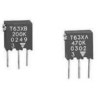
... 0. during 6 h 200 cycles Contact res. variation: < MARKING TYPICAL • Vishay trademark TCR MAX °C • Model WIPER + 125 °C CUR. • Style mA ppm/°C • Ohmic value (in Ω, kΩ, MΩ) • Tolerance (in %) only if non standard ...

Page 4

... T63 Vishay Sfernice ORDERING INFORMATION (Part Number Model STYLE T63 DESCRIPTION (for information only) T63 XA MODEL STYLE www.vishay.com 70 See also Application Note: 1/4" Multi-Turn Fully Sealed Container Cermet Trimmer OHMIC VALUE TOLERANCE From Ω to 2.2 MΩ on request 104 = 100 kΩ 100K ...

Page 5

... Vishay product could result in personal injury or death. Customers using or selling Vishay products not expressly indicated for use in such applications their own risk and agree to fully indemnify and hold Vishay and its distributors harmless from and against any and all claims, liabilities, expenses and damages arising or resulting in connection with such use or sale, including attorneys fees, even if such claim alleges that Vishay or its distributor was negligent regarding the design or manufacture of the part ...

Related keywords