0W344-005-XTP ON Semiconductor, 0W344-005-XTP Datasheet
0W344-005-XTP
Specifications of 0W344-005-XTP


Related parts for 0W344-005-XTP


0W344-005-XTP Summary of contents
Page 1
... General Description BelaSigna 200 is a high-performance, programmable, mixed-signal digital signal processor (DSP) that is based on ON Semiconductor’s patented second-generation SignaKlara™ technology. This single-chip solution is ideally suited for embedded applications where audio performance, low power consumption and miniaturization are critical. BelaSigna 200 targets a wide variety of digital speech- and audio-centric applications, including: ...
Page 2
BelaSigna 200 2.0 Key Features 2.1 System • 16-bit programmable fixed-point DSP core • Configurable WOLA filterbank coprocessor optimized for filterbank calculations • 12-Kword program memory (PRAM) • Two 4-Kword data memories (XRAM and YRAM) • Two 384-word dual-port FIFO ...
Page 3
BelaSigna 200 2.5 Input Stage • Two separate input channels, each with two multiplexed inputs • Two configurable preamplifiers for improved input dynamic range matching • Two analog third-order anti-aliasing filters • Two 16-bit oversampling ΣΔ A/D converters • Two ...
Page 4
BelaSigna 200 3.0 BelaSigna 200 Design and Layout Strategies BelaSigna 200 is designed to allow both digital and analog processing in a single system. Due to the mixed-signal nature of this system, the design of the printed circuit board (PCB) ...
Page 5
BelaSigna 200 digital pads of BelaSigna 200 itself. Analog ground returns associated with the audio output stage should connect back to the star point on separate individual traces. For more information on the recommended ground design strategy, see Table 1. ...
Page 6
BelaSigna 200 Table 2: Non-Critical Signal Pin Name CAP0, CAP1 DEBUG_TX, DEBUG_RX TWSS_SDA, TWSS_CLK GPIO[14..0] GPIO[15] UART_RX, UART_TX PCM_FRAME, PCM_CLK, PCM_OUT, PCM_IN I2S_INA, I2S_IND, I2S_FA, I2S_FD, I2S_OUTA, I2S_OUTD DCLK LSAD[5..0] SPI_CLK, SPI_CS, SPI_SERI, SPI_SERO 3.3 Audio Inputs The audio input ...
Page 7
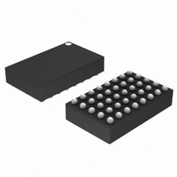
BelaSigna 200 4.0 Mechanical and Environmental Information BelaSigna 200 is available in two packages: • The QFN package measures 8x8mm, has easy-to-probe signals and all I/O available. • The CSP package is the ultra-miniature option, measuring only 2.3x3.7mm; this package ...
Page 8
BelaSigna 200 4.1.2. QFN Pad Out Pad # Pad Name Pad Function 1 CAP0 Charge pump capacitor pin 0 2 VDBL Double voltage 3 A|0 Audio signal input to ADC0 4 A|1/LOUT Audio signal input to ADC0/line level output signal ...
Page 9
... QFN Carrier Information ON Semiconductor offers tape and reel packing for BelaSigna 200 QFN packages. The packing consists of a pocketed carrier tape, a cover tape, and a molded anti-static polystyrene reel. The carrier and cover tape create an ESD safe environment, protecting the QFNs from physical and electro-static damage during shipping and handling ...
Page 10
BelaSigna 200 Notes sprocket hole pitch cumulative tolerance ± 0.02. 2. Camber not to exceed 100 mm. 3. Material: PS+C. and Bo measured on a plane 0.3 mm above the bottom of the ...
Page 11
BelaSigna 200 4.2 CSP Package Option 4.2.1. CSP Mechanical Information Figure 7: CSP Mechanical Drawings Rev Page www.onsemi.com ...
Page 12
BelaSigna 200 4.2.2. CSP Pad Out Table 4: Pad Out (Advance Information) Pad Pad Name Pad Function Index B2 CAP0 Charge pump capacitor pin 0 A2 CAP1 Charge pump capacitor pin 1 A1 VDBL Double voltage C3 VREG Regulated voltage ...
Page 13
... QFN). This reduction eliminates access to GPIOs (0,1,2,6,15), LSAD 2, the I2S interface, and the IR remote receiver. For PCB manufacture with BelaSigna 200 CSP, ON Semiconductor recommends Solder-on-Pad (SoP) surface finish. With SoP, the solder mask opening should be solder mask-defined and copper pad geometry will be dictated by the PCB vendor’s design requirements ...
Page 14
... ON Semiconductor can provide BelaSigna 200 CSP landpattern CAD files to assist your PCB design upon request. Rev Page www.onsemi.com ...
Page 15
... BAT and BOS provide all the common processing routines in an easy-to-call macro structure. This streamlines the assembly level coding by encapsulating redundant work, while maintaining the true efficiency of hardware-level coding. For advanced DSP developers or application developers, ON Semiconductor provides an application development extension to the EDK, which contains the following: • ...
Page 16
BelaSigna 200 6.0 Architecture Overview 6.1 RCore DSP The RCore is a 16-bit fixed-point, dual-Harvard-architecture DSP. It includes efficient normalize and de-normalize instructions, plus support for double-precision operations to provide the additional dynamic range needed for many applications. All memory ...
Page 17
BelaSigna 200 6.1.2. Instruction Set The RCore instruction set can be divided into the following three classes: 1. Arithmetic and Logic Instructions The RCore uses two's complement fractional as a native data format. Thus, the range of valid numbers is ...
Page 18
BelaSigna 200 7.0 Instruction Set Table 6: Instruction Set Instruction Description ABS A [,Cond] [,DW] Calculate absolute value condition ADD A, Reg [,C] Add register to A ADD A, (Rij) [,C] Add memory to A ADD A, ...
Page 19
BelaSigna 200 Table 7: Instruction Set Continued Instruction Description Load loop counter with 8-bit unsigned LDLC0/1 SIMM SIMM LDSI A, SIMM Load A with signed SIMM Load pointer register with unsigned LDSI Rij, SIMM SIMM MLD (Rj), (Ri) [,SQ] Multiplier ...
Page 20
BelaSigna 200 7.1 Weighted Overlap-Add (WOLA) Filterbank Coprocessor The WOLA coprocessor performs low-delay, high-fidelity filterbank processing to provide efficient time-frequency processing. The coprocessor stores intermediate data values, program code and window coefficients in its own memory space. Audio data are ...
Page 21
BelaSigna 200 The IOP places and retrieves FIFO data in memories shared with the RCore. Each FIFO (input and output) has two memory interfaces. The first corresponds with the normal FIFO. Here the address of the most recent input block ...
Page 22
BelaSigna 200 7.6 Interrupts The RCore DSP has a single interrupt channel that serves eleven interrupt sources in a prioritized manner. The interrupt controller also handles interrupt acknowledge flags. Every interrupt source has its own interrupt vector. Furthermore, the priority ...
Page 23
BelaSigna 200 Table 9: Interrupts Interrupt Description WOLA_DONE WOLA function done IO_BLOCK_FULL IOP interrupt PCM PCM interface interrupt UART_RX General-purpose UART receive interrupt UART_TX General-purpose UART transmit interrupt GP_TIMER General-purpose timer interrupt WATCHDOG_TIMER Watchdog timer interrupt SPI_INTERFACE SPI interface interrupt ...
Page 24
BelaSigna 200 8.0 Description of Analog Blocks 8.1 Input Stage The analog audio input stage is comprised of two individual channels. For each channel, one of two possible inputs is routed to the input of the programmable preamplifier that can ...
Page 25
BelaSigna 200 Two analog outputs designed to drive external amplifiers are also available. 8.3 Clock-Generation Circuitry BelaSigna 200 operates with two main clock domains: a domain running on the system clock (SYS_CLK) and a domain running on the main clock ...
Page 26
BelaSigna 200 9.0 External Interfaces 9.1 External Digital Interfaces 9.1.1. Pulse-Code Modulation Interface (PCM I/F) The PCM interface is a bi-directional, four-wire synchronous serial interface suitable for high-speed digital audio transfer. This externally-clocked interface is capable of sending data serially ...
Page 27
BelaSigna 200 9.2 External Analog Interfaces 9.2.1. Low-Speed A/D Converters (LSAD) Six LSAD inputs are available on BelaSigna 200. Combined with two internal LSAD inputs (supply and ground) this gives a total of eight multiplexed inputs to the LSAD converter. ...
Page 28
... Once the bootloader is loaded into PRAM the program counter is set to point to the beginning of the bootloader code. Subsequently, the signal-processing application that is stored in the EEPROM is downloaded to PRAM by the bootloader. The boot process generally takes less than one second. ON Semiconductor provides a standard full-featured bootloader. An alternative to bootloading is often used in development - program code can be loaded through the debug port after powering BelaSigna 200 ...
Page 29
BelaSigna 200 11.0 Electrical Characteristics 11.1 Absolute Maximum Ratings Table 10: Absolute Maximum Ratings Parameter Supply voltage 2 Operating temperature range Storage temperature range Voltage at any input pin Caution: Class 2 ESD sensitivity, JESD22-A114-B (2000V) 11.2 Electrical Characteristics Conditions: ...
Page 30
BelaSigna 200 11.3 Analog Characteristics Conditions: Temperature = 25°C, f SYS_CLK Table 12: Analog Characteristics Parameter Input Stage Input voltage 5 Input impedance Input referred noise Input dynamic range Input THD+N Preamplifier gain tolerance (0, 12, 15, 18, 21, 24, ...
Page 31
BelaSigna 200 11.4 Digital Characteristics Conditions: Temperature = 25°C, f SYS_CLK Table 13: Digital Characteristics Parameter Output Stage Direct digital output load current Direct digital output resistance Direct digital output 0 dynamic range Direct digital output 0 THD+N Direct digital ...
Page 32
BelaSigna 200 12.0 Timing Diagrams 12.1 PCM Interface Timing Diagrams 12.1.1. 16-bit Figure 14: LSB Advanced Short Figure 15: LSB Advanced Wide Rev Page www.onsemi.com ...
Page 33
BelaSigna 200 Figure 16: LSB Del Short Figure 17: LSB Del Wide Rev Page www.onsemi.com ...
Page 34
BelaSigna 200 Figure 18: MSB Advanced Short Figure 19: MSB Advanced Wide Rev Page www.onsemi.com ...
Page 35
BelaSigna 200 Figure 20: MSB Del Short Figure 21: MSB Del Wide Rev Page www.onsemi.com ...
Page 36
BelaSigna 200 12.1.2. 32-bit Figure 22: LSB Advanced Short Figure 23: LSB Advanced Wide Rev Page www.onsemi.com ...
Page 37
BelaSigna 200 Figure 24: LSB Del Short Figure 25: LSB Del Wide Rev Page www.onsemi.com ...
Page 38
BelaSigna 200 Figure 26: MSB Advanced Short Figure 27: MSB Advanced Wide Rev Page www.onsemi.com ...
Page 39
BelaSigna 200 Table 14: PCM Inter face Descripti ons Parameter Description T PCM_CLK high to data valid dv T Setup time before PCM_CLK high s T PCM_CLK high to PCM_FRAME high fr T PCM_CLK high period (1.28MHz PCM_CLK ...
Page 40
BelaSigna 200 12.2 GPIO Timing Diagram Table 15: GPIO Interface Descriptions Parameter Description T SYS_CLK high to data valid dv T Setup time before SYS_CLK high s T SYS_CLK high period (1.28MHz SYS_CLK low period (1.28MHz) cl Figure ...
Page 41
BelaSigna 200 12.3 SPI Port Timing Diagram Table 16: SPI Interface Descriptions Parameter Description T SPI_CLK high to output data valid dv T Setup time before SPI_CLK high s T SPI_CS low to first SPI_CLK high fce Figure 31: SPI ...
Page 42
... Time within 5°C of Actual Peak Temperature Ramp-Down Rate Time 25°C to Peak Temperature All BelaSigna 200 QFNs with part number revisions 003 (i.e. 0W344-003-XTP) and higher are Pb-free and should follow the re-flow guidelines for Pb-free assemblies. All BelaSigna 200 CSPs are Pb-free. 14.0 ESD Sensitive Device CAUTION: Electrostatic discharge (ESD) sensitive device ...
Page 43
... BelaSigna 200 16.0 Ordering Information Part Number Package 0W344-004-XTP 8x8mm QFN 0W344-005-XTP 8x8mm QFN 0W588-002-XUA 2.3x2.8mm WLCSP 17.0 Company or Product Inquiries For more information about ON Semiconductor’s products or services visit our Web site at http://onsemi.com. ON Semiconductor and are registered trademarks of Semiconductor Components Industries, LLC (SCILLC). SCILLC reserves the right to make changes without further notice to any products herein. SCILLC makes no warranty, representation or guarantee regarding the suitability of its products for any particular purpose, nor does SCILLC assume any liability arising out of the application or use of any product or circuit, and specifically disclaims any and all liability, including without limitation special, consequential or incidental damages. “ ...