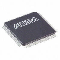
EP1K10TC100-3 Altera, EP1K10TC100-3 Datasheet - Page 22

EP1K10TC100-3
Manufacturer Part Number
EP1K10TC100-3
Description
IC ACEX 1K FPGA 10K 100-TQFP
Manufacturer
Altera
Series
ACEX-1K®r
Datasheet
1.EP1K10TC100-3N.pdf
(86 pages)
Specifications of EP1K10TC100-3
Number Of Logic Elements/cells
576
Number Of Labs/clbs
72
Total Ram Bits
12288
Number Of I /o
66
Number Of Gates
56000
Voltage - Supply
2.375 V ~ 2.625 V
Mounting Type
Surface Mount
Operating Temperature
0°C ~ 70°C
Package / Case
100-TQFP, 100-VQFP
Lead Free Status / RoHS Status
Contains lead / RoHS non-compliant
Other names
544-1027
Available stocks
Company
Part Number
Manufacturer
Quantity
Price
Part Number:
EP1K10TC100-3
Manufacturer:
ALTERA/阿尔特拉
Quantity:
20 000
Part Number:
EP1K10TC100-3N
Manufacturer:
ALTERA/阿尔特拉
Quantity:
20 000
ACEX 1K Programmable Logic Device Family Data Sheet
22
Normal Mode
The normal mode is suitable for general logic applications and wide
decoding functions that can take advantage of a cascade chain. In normal
mode, four data inputs from the LAB local interconnect and the carry-in
are inputs to a 4-input LUT. The compiler automatically selects the carry-
in or the DATA3 signal as one of the inputs to the LUT. The LUT output
can be combined with the cascade-in signal to form a cascade chain
through the cascade-out signal. Either the register or the LUT can be used
to drive both the local interconnect and the FastTrack Interconnect routing
structure at the same time.
The LUT and the register in the LE can be used independently (register
packing). To support register packing, the LE has two outputs; one drives
the local interconnect, and the other drives the FastTrack Interconnect
routing structure. The DATA4 signal can drive the register directly,
allowing the LUT to compute a function that is independent of the
registered signal; a 3-input function can be computed in the LUT, and a
fourth independent signal can be registered. Alternatively, a 4-input
function can be generated, and one of the inputs to this function can be
used to drive the register. The register in a packed LE can still use the clock
enable, clear, and preset signals in the LE. In a packed LE, the register can
drive the FastTrack Interconnect routing structure while the LUT drives
the local interconnect, or vice versa.
Arithmetic Mode
The arithmetic mode offers two 3-input LUTs that are ideal for
implementing adders, accumulators, and comparators. One LUT
computes a 3-input function; the other generates a carry output. As shown
in
from the LAB local interconnect to generate a combinatorial or registered
output. For example, in an adder, this output is the sum of three signals:
a, b, and carry-in. The second LUT uses the same three signals to generate
a carry-out signal, thereby creating a carry chain. The arithmetic mode
also supports simultaneous use of the cascade chain.
Up/Down Counter Mode
The up/down counter mode offers counter enable, clock enable,
synchronous up/down control, and data loading options. These control
signals are generated by the data inputs from the LAB local interconnect,
the carry-in signal, and output feedback from the programmable register.
Two 3-input LUTs are used; one generates the counter data, and the other
generates the fast carry bit. A 2-to-1 multiplexer provides synchronous
loading. Data can also be loaded asynchronously with the clear and preset
register control signals without using the LUT resources.
Figure 11,
the first LUT uses the carry-in signal and two data inputs
Altera Corporation


