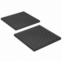
XC3S250E-4FTG256C Xilinx Inc, XC3S250E-4FTG256C Datasheet - Page 70

XC3S250E-4FTG256C
Manufacturer Part Number
XC3S250E-4FTG256C
Description
IC SPARTAN-3E FPGA 250K 256-FTBG
Manufacturer
Xilinx Inc
Series
Spartan™-3Er
Datasheet
1.XC3S100E-4VQG100C.pdf
(233 pages)
Specifications of XC3S250E-4FTG256C
Total Ram Bits
221184
Number Of Logic Elements/cells
5508
Number Of Labs/clbs
612
Number Of I /o
172
Number Of Gates
250000
Voltage - Supply
1.14 V ~ 1.26 V
Mounting Type
Surface Mount
Operating Temperature
0°C ~ 85°C
Package / Case
256-LBGA
No. Of Logic Blocks
5508
No. Of Gates
250000
No. Of Macrocells
5508
No. Of Speed Grades
4
No. Of I/o's
190
Clock Management
DLL
Lead Free Status / RoHS Status
Lead free / RoHS Compliant
Other names
122-1482
Available stocks
Company
Part Number
Manufacturer
Quantity
Price
Company:
Part Number:
XC3S250E-4FTG256C
Manufacturer:
TOS
Quantity:
3 012
Company:
Part Number:
XC3S250E-4FTG256C
Manufacturer:
XILINX
Quantity:
281
Part Number:
XC3S250E-4FTG256C
Manufacturer:
ALTERA/阿尔特拉
Quantity:
20 000
Functional Description
JTAG boundary-scan pins: TDI, TDO, TMS, and TCK. All
other configuration pins are dual-purpose I/O pins and are
available to the FPGA application after the DONE pin goes
High. See
Table 47
ous configuration pins during the configuration process. The
configuration interface is designed primarily for 2.5V opera-
tion when the VCCO_2 (and VCCO_1 in BPI mode) con-
nects to 2.5V.
The configuration pins also operate at other voltages by set-
ting VCCO_2 (and VCCO_1 in BPI mode) to either 3.3V or
1.8V. The change on the V
characteristics, including the effective IOSTANDARD. For
example, with V
be similar to those of LVCMOS33, and the current when
driving High, I
while the current when driving Low, I
V
those of LVCMOS18, and the current when driving High,
I
the current when driving Low, I
put voltages are determined by the V
for 1.8V, LVCMOS25 for 2.5V, and LVCMOS33 for 3.3V. For
more details see UG332.
CCLK Design Considerations
For additional information, refer to the “Configuration Pins
and Behavior during Configuration” chapter in UG332.
The FPGA’s configuration process is controlled by the
CCLK configuration clock. Consequently, signal integrity of
CCLK is important to guarantee successful configuration.
Poor CCLK signal integrity caused by ringing or reflections
might cause double-clocking, causing the configuration pro-
cess to fail.
Although the CCLK frequency is relatively low, Spartan-3E
FPGA output edge rates are fast. Therefore, careful atten-
tion must be paid to the CCLK signal integrity on the printed
circuit board. Signal integrity simulation with IBIS is recom-
mended. For all configuration modes except JTAG, the sig-
nal integrity must be considered at every CCLK trace
destination, including the FPGA’s CCLK pin.
This analysis is especially important when the FPGA
re-uses the CCLK pin as a user-I/O after configuration. In
these cases, there might be unrelated devices attached to
CCLK, which add additional trace length and signal destina-
tions.
70
OH
CCO
, decreases slightly to approximately 6 to 8 mA. Again,
= 1.8V, the output characteristics will be similar to
shows the default I/O standard setting for the vari-
Start-Up
OH
CCO
, increases to approximately 12 to 16 mA,
for additional information.
= 3.3V, the output characteristics will
CCO
supply also changes the I/O
OL
, remains 8 mA. The out-
CCO
OL
, remains 8 mA. At
level, LVCMOS18
www.xilinx.com
In the Master Serial, SPI, and BPI configuration modes, the
FPGA drives the CCLK pin and CCLK should be treated as
a full bidirectional I/O pin for signal integrity analysis. In BPI
mode, CCLK is only used in multi-FPGA daisy-chains.
The best signal integrity is ensured by following these basic
PCB guidelines:
•
•
•
•
Design Considerations for the HSWAP, M[2:0],
and VS[2:0] Pins
For additional information, refer to the “Configuration Pins
and Behavior during Configuration” chapter in UG332.
Unlike previous Spartan FPGA families, nearly all of the
Spartan-3E dual-purpose configuration pins are available
as full-featured user I/O pins after successful configuration,
when the DONE output goes High.
The HSWAP pin, the mode select pins (M[2:0]), and the
variant-select pins (VS[2:0]) must have valid and stable
logic values at the start of configuration. VS[2:0] are only
used in the SPI configuration mode. The levels on the
M[2:0] pins and VS[2:0] pins are sampled when the INIT_B
pin returns High. See
The HSWAP pin defines whether FPGA user I/O pins have
a pull-up resistor connected to their associated V
ply pin during configuration or not, as shown
HSWAP must be valid at the start of configuration and
remain constant throughout the configuration process.
Table 48: HSWAP Behavior
HSWAP
Value
Route the CCLK signal as a 50
controlled-impedance transmission line.
Route the CCLK signal without any branching. Do not
use a “star” topology.
Keep stubs, if required, shorter than 10 mm (0.4
inches).
Terminate the end of the CCLK transmission line.
0
1
Pull-up resistors connect to the associated
V
I/O pins during configuration. Pull-up resistors
are active until configuration completes.
Pull-up resistors disabled during configuration.
All user-I/O or dual-purpose I/O pins are in a
high-impedance state.
CCO
supply for all user-I/O or dual-purpose
Figure 77
Description
DS312-2 (v3.8) August 26, 2009
for a timing example.
Ω
Product Specification
CCO
Table
sup-
48.
R


