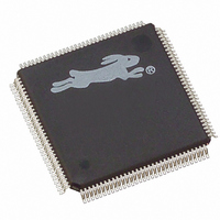
20-668-0011 Rabbit Semiconductor, 20-668-0011 Datasheet - Page 36

20-668-0011
Manufacturer Part Number
20-668-0011
Description
IC MPU RABIT3000A 55.5MHZ128LQFP
Manufacturer
Rabbit Semiconductor
Datasheet
1.20-668-0011.pdf
(312 pages)
Specifications of 20-668-0011
Processor Type
Rabbit 3000 8-Bit
Speed
55.5MHz
Voltage
2.5V, 2.7V, 3V, 3.3V
Mounting Type
Surface Mount
Package / Case
128-LQFP
Data Bus Width
8 bit
Maximum Clock Frequency
55.5 MHz
Operating Supply Voltage
1.8 V to 3.6 V
Maximum Operating Temperature
+ 85 C
Mounting Style
SMD/SMT
Minimum Operating Temperature
- 55 C
Number Of Programmable I/os
56
Lead Free Status / RoHS Status
Lead free / RoHS Compliant
Features
-
Lead Free Status / Rohs Status
Lead free / RoHS Compliant
Other names
316-1061
Available stocks
Company
Part Number
Manufacturer
Quantity
Price
Company:
Part Number:
20-668-0011
Manufacturer:
Rabbit Semiconductor
Quantity:
10 000
- Current page: 36 of 312
- Download datasheet (2Mb)
The processor checks the SMODE pins after the /RESET signal is inactive. Table 3-2
summarizes what happens:
• If both SMODE pins are zero, the Rabbit 3000 begins fetching instructions from the
• If either of the SMODE pins is high, the processor will enter the bootstrap mode and
In bootstrap mode, the processor inhibits the normal memory fetch from /CS0 and instead
fetches instructions from a small internal boot ROM. This program reads triplets of three
bytes from the selected peripheral. The first byte is the most-significant byte of a 16-bit
address, the second byte is the least-significant byte of the address, and the third byte is
the data to be written. If the uppermost bit of the address is 1, then the address is assumed
to be an internal register address instead of a memory address, and the data are written to
the appropriate register instead.
The boot ROM program waits for data to be available; each byte received automatically
resets the watchdog timer with a 2-second timeout. Bytes must be received quickly
enough to prevent timeout (or the watchdog must be disabled).
The device checks the state of the SMODE pins each time it jumps back to the start of the
ROM program and responds according to the current state. In addition, by writing to bit 7
of the Slave Port Control Register (SPCR) the processor can be told to ignore the state of
the SMODE pins and continue normal operation.
Note that the processor can be told to reenter bootstrap mode at any time by setting bit 7 of
SPCR low; once this occurs and the least-significant four bits of the current PC address
are zero, the processor will sample the state of the SMODE pins and respond accordingly.
This feature allows in-line downloading from the selected bootstrap port; once the down-
load is complete, bit 7 of SPCR can be set high and the processor will continue operating
from where it left off.
As a security feature, any attempt to enter bootstrap mode from either the SMODE pins or
by writing to bit 7 of SPCR will erase the data stored in the onchip-encryption RAM. This
prevents loading a small program in memory to read out the data.
26
memory device on /CS0 and /OE0.
accept triplets from either Serial Port A or the slave port. It is good practice to place
pulldown resistors on the SMODE pins to ensure proper operation of your design.
SMODE Pins [1,0]
00
01
10
11
Table 3-2. SMODE Pin Settings
No bootstrap; code is fetched from address 0x0000
on /CS0, /OE0.
Bootstrap from the slave port.
Bootstrap from Serial Port A, clocked mode.
Bootstrap from Serial Port A, asynchronous mode.
Operation
Rabbit 3000 Microprocessor User’s Manual
Related parts for 20-668-0011
Image
Part Number
Description
Manufacturer
Datasheet
Request
R

Part Number:
Description:
IC CPU RABBIT2000 30MHZ 100PQFP
Manufacturer:
Rabbit Semiconductor
Datasheet:

Part Number:
Description:
IC CPU RABBIT4000 128-LQFP
Manufacturer:
Rabbit Semiconductor
Datasheet:

Part Number:
Description:
Microprocessors - MPU Rabbit 3000 TFBGA Microprocessor
Manufacturer:
Rabbit Semiconductor

Part Number:
Description:
Microprocessors - MPU Rabbit 4000 LQFP Microprocessor
Manufacturer:
Rabbit Semiconductor

Part Number:
Description:
IC, I/O EXPANDER, 8BIT, 40MHZ, TQFP-64
Manufacturer:
Rabbit Semiconductor

Part Number:
Description:
SCRs 1.5A 200uA 400V Sensing
Manufacturer:
Littelfuse Inc
Datasheet:

Part Number:
Description:
CARD 6-RELAY SMARTSTAR SR9500
Manufacturer:
Rabbit Semiconductor
Datasheet:

Part Number:
Description:
WIRE-BOARD CONN RECEPTACLE, 6POS, 3.96MM
Manufacturer:
TE Connectivity
Datasheet:

Part Number:
Description:
ADAPTER 20 PIN .420" PLUGS(6PCS)
Manufacturer:
Logical Systems Inc.
Datasheet:

Part Number:
Description:
CONN BARRIER BLOCK .438" 20 POS
Manufacturer:
Cinch Connectors
Datasheet:

Part Number:
Description:
20 MODII 2PC HDR DR SHRD, ROHS
Manufacturer:
TE Connectivity
Datasheet:

Part Number:
Description:
WIRE-BOARD CONN RECEPTACLE, 6POS, 3.96MM
Manufacturer:
TE Connectivity
Datasheet:


