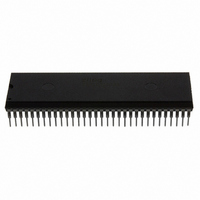
Z8S18010PSG Zilog, Z8S18010PSG Datasheet - Page 43

Z8S18010PSG
Manufacturer Part Number
Z8S18010PSG
Description
IC 10MHZ STATIC Z180 64-DIP
Manufacturer
Zilog
Datasheet
1.Z8S18010PSG.pdf
(71 pages)
Specifications of Z8S18010PSG
Processor Type
Z180
Features
Enhanced Z180
Speed
10MHz
Voltage
5V
Mounting Type
Through Hole
Package / Case
64-DIP (0.750", 19.05mm)
Processor Series
Z8S180X
Core
Z80
Data Bus Width
8 bit
Maximum Clock Frequency
10 MHz
Number Of Timers
2
Operating Supply Voltage
0 V to 3.3 V
Maximum Operating Temperature
+ 70 C
Mounting Style
Through Hole
Development Tools By Supplier
Z8S18000ZEM
Minimum Operating Temperature
0 C
Lead Free Status / RoHS Status
Lead free / RoHS Compliant
Other names
269-4297
Z8S18010PSG
Z8S18010PSG
Available stocks
Company
Part Number
Manufacturer
Quantity
Price
Company:
Part Number:
Z8S18010PSG
Manufacturer:
Zilog
Quantity:
48
the data format is configured for multiprocessor mode based
on
cleared to
ZiLOG
processor communication format is selected (
If
0
fined during and after
bits) in
Multiprocessor (
parity. If
For channel 1, the
(Clocked Serial Receive Data). Thus,
when read if the channel 1
input pin function is selected. The
is not affected by
If the
mode bit in the
sets the prescale (PS) control. Under those circumstances,
a
indicates divide-by-30. The bit resets to
, then
0
indicates a divide-by-10 prescale function while a
input pin is High,
is used to specify the
When the
ited (that is, held at ).
,
reflects the state of the external
(number of data bits) and
0
1
during
bits in this register are not
, then
. The format is as follows:
, and may include parity. The
0
0
is transmitted. The
, the data format is based on
input pin is High, the
register is
input is multiplexed with
.
) format offers no provision for
.
.
is transmitted. If
is read as
data bit for transmission.
0
, then writing to this bit
When
bit =
0
.
1
W h e n
1
data of
(number of stop
.
, and the
state is unde-
and the
When multi-
is only valid
input. If the
is set to
bit is inhib-
bit = ),
r e a d ,
bit is
pin
1
1
,
,
parity.
(
is selected. If
cleared to
ister is
rate from the data sampling clock. If
by-16 is used, while if
if these bits are
pin is used as a clock input, and is divided by 1, 16, or 64
depending on the
ister.
If these bits are not
is
Setting or leaving these bits as
nel only when its
tem Configuration Register is
0
is cleared to
, then these bits specify a power-of-two divider for the
clock as indicated in Table 10.
function when bit
0
bit of
, this bit specifies the divider used to obtain baud
0
does not affect the enabling/disabling of parity
offers the
during
0
is set to
during
, as they are after a
bit and the
). If
pin is selected for the
0
and the
of the Interrupt Edge register is
If the
is set to
1
.
, odd parity is selected.
function when bit 4 of the Sys-
is cleared to
0
.
.
1
makes sense for a chan-
, divide-by-64 is used.
bit in the
bit in the
selects oven or odd
mode bit is
is reset to
/
0
, even parity
, the
offers the
0
function.
, divide-
F i r s t ,
reg-
reg-
1
is
.


