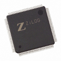
Z8018233ASG Zilog, Z8018233ASG Datasheet - Page 24

Z8018233ASG
Manufacturer Part Number
Z8018233ASG
Description
IC 33MHZ STATIC MIMIC 100-LQFP
Manufacturer
Zilog
Datasheet
1.Z8018233FSG.pdf
(109 pages)
Specifications of Z8018233ASG
Processor Type
Z180
Features
Smart Peripheral Controller
Speed
33MHz
Voltage
5V
Mounting Type
Surface Mount
Package / Case
100-LQFP
Processor Series
Z8018xx
Core
Z80
Data Bus Width
8 bit
Program Memory Type
ROMLess
Interface Type
UART
Maximum Clock Frequency
33 MHz
Number Of Programmable I/os
24
Number Of Timers
2
Operating Supply Voltage
4.5 V to 5.5 V
Maximum Operating Temperature
+ 70 C
Mounting Style
SMD/SMT
Minimum Operating Temperature
0 C
Lead Free Status / RoHS Status
Lead free / RoHS Compliant
Available stocks
Company
Part Number
Manufacturer
Quantity
Price
Zilog
16550 MIMIC FIFO DESCRIPTION (Continued)
3-24
The PC interface may be interrupted when 1, 4, 8 or 14
bytes are available in the receiver FIFO by setting bits 6
and 7 in the FCR (FIFO Control Register, PC address 02H)
to the appropriate value. If the FIFO is not empty, but below
the above trigger value, a timeout interrupt is available if
the receiver FIFO is not written by the MPU or read by the
PC from an interval determined by the Character Timeout
Timer. This is an additional Timer with MPU access only
that is used to emulate the 16550 4 character timeout
delay.
The Receive FIFO timeout timers are designed to reload
and begin countdown after every read or write of the Rx
FIFO, regardless of the Rx trigger level or number of bytes
in the FIFO. Therefore, it is possible to get Timeout interrupts
more often than Receive data interrupts. In order to closely
emulate a 16550, a receive timeout timer enhancement is
provided. When enabling this feature, the timeout timer will
not begin counting down until the character emulation
timer for each byte of data in the Rx FIFO has expired.
Note: Enabling this feature will facilitate increased
16550 compatibility but may impede throughput. If the
Receive Timeout interrupt occurs, the PC HOST will only
be allowed to read up to 4-5 consecutive characters
before the Data Ready bit is forced to zero (even if there
is still more data in FIFO). This is required to maintain
character pacing.
(MPU Side Read)
MPU Side
Interface
Databus
Control
Register
CNTL
MPU
FIFO
MPU
MPU
Line
IRQ
Internal Clock
Sync
Figure 8. 16550 MIMIC Transmitter FIFO Block Diagram
5
8
R
E
A
D
B
U
F
F
E
R
Pointer
Read
PS009801-0301
P R E L I M I N A R Y
Data Bits
ALU
16x8
The timer receives the ESCC /TRxCB as its input clock.
Software must determine the correct values to program
into the Receiver Timeout register and the ESCC TRxCB to
achieve the correct delay interval for timeout. These
interrupts are cleared by the FIFO reaching the trigger
point or by resetting the Timeout Interval Timer by FIFO
MPU write or PC read access.
With FIFO mode enabled, the MPU is interrupted when the
receiver FIFO is empty, corresponding to bit 5 being set
in the IUS/IP register (MPU access only). This bit
corresponds to a PC read of the receive buffer in non-FIFO
(16450) mode. The interrupt source is cleared when the
FIFO becomes non-empty or the MPU reads the IUS/IP
register.
The transmitter FIFO is 16-byte FIFO with PC write and
MPU read access (Figure 8). In FIFO mode, the PC
receives an interrupt when the transmitter becomes empty
corresponding to bit 5 being set in the LSR. This bit and the
interrupt source are cleared when the transmit FIFO
becomes non-empty or the Interrupt Identification Register
(IIR) register is read by the PC.
Pointer
Write
W
R
T
E
B
U
F
F
E
R
I
Internal Clock
8
Sync
Z
ILOG
I
NTELLIGENT
PC Side
Databus
(PC Side Write)
Internal
Clock
PC
Cntrl
Line
PC
IRQ
16550
MIMIC or
PC Side
Interface
DS971820600
Z80182/Z8L182
P
ERIPHERAL


