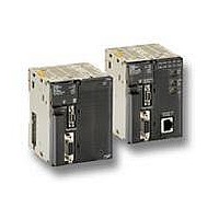
CJ1M-CPU11 Omron, CJ1M-CPU11 Datasheet - Page 20

CJ1M-CPU11
Manufacturer Part Number
CJ1M-CPU11
Description
Controllers CPU 5k PROG 32k DATA MEMORY
Manufacturer
Omron
Specifications of CJ1M-CPU11
Lead Free Status / Rohs Status
Lead free / RoHS Compliant
Available stocks
Company
Part Number
Manufacturer
Quantity
Price
Company:
Part Number:
CJ1M-CPU11
Manufacturer:
ABB
Quantity:
100
CJ1M CPU (Only) Specifications
J Pulse Input Specifications
Interrupt Inputs and Quick-Response Inputs
J High-Speed Counter Input
CPU Overview
B-30
Item
Number of interrupt and
quick-response input points
Interrupt
inputs
Quick-response input
Item
Number of high-speed counter
inputs
Counter modes
(set in the PC Setup)
Response frequency
Counter type
Counting range
High-speed counter present value
storage words
Control method
Counter reset method
Programmable Controller
Interrupt input mode
Counter mode
Line driver
input
24-VDC
input
Specifications
4 total
At the rising or falling edge of the input signal, the CPU’s cyclic program is interrupted and the
corresponding I/O interrupt task (task number 140 to 143) is executed. The response time (i.e.,
the time from the input condition being satisfied until execution of the interrupt task) is 20 µs max.
The number of rising or falling edges of the input signal are counted incrementally or
decrementally, and when the count has been reached, the corresponding interrupt task (task
number 140 to 143) is executed. The input response frequency is 1 kHz.
Signals less than the cycle time (30 µs min.) can be treated as ON signals for one cycle.
Specification
2 (high-speed counters 0 and 1)
Phase differential
inputs (phase-A, -B,
and -Z inputs)
50 kHz
30 kHz
Linear counter or circular counter (set in the PC Setup)
Linear counter: 8000 0000 to 7FFF FFFF Hex
Circular counter: 0000 0000 to circular counter set value
(The circular counter set value is set in the PC Setup in the range 0000 0001 to FFFF FFFF
Hex.)
High-speed counter 0: A270 (upper digits) and A271 (lower digits)
High-speed counter 1: A272 (upper digits) and A273 (lower digits)
Target value comparison inputs and range comparison inputs are possible for these values.
Note: The present values are updated each cycle as part of common processing. Use the PRV
Target value comparison: Up to 48 target values and interrupt task numbers can be registered.
Range comparison: Up to 8 upper limits, lower limits, and interrupt task numbers can be
registered.
Z-phase signal + software reset: Counter reset when the Z-phase input is turned ON with the
reset bit (see below) ON.
Software reset: Counter reset when the reset bit (see below) turns ON.
Reset bit: A531, bit 00 (high-speed counter 0); A531, bit 01 (high-speed counter 1)
CJ1
instruction to read the latest value.
Up and down pulse
inputs (incremental
pulse, decremental
pulse, and reset
inputs)
100 kHz
60 kHz
Pulse + direction
inputs (pulse,
direction, and reset
inputs)
100 kHz
60 kHz
Incremental pulse input
(incremental pulse and
reset inputs)
100 kHz
60 kHz


