LSXF3K Honeywell, LSXF3K Datasheet

Basic / Snap Action / Limit Switches Hazardous Location/ Single Pole LSX

LSXF3K

Manufacturer Part Number
LSXF3K
Description
Basic / Snap Action / Limit Switches Hazardous Location/ Single Pole LSX
Manufacturer
Honeywell
Datasheet

Specifications of LSXF3K

Contact Form
SPDT - 1 NC / 1 NO
Contact Rating
10 Amps
Actuator
Roller Plunger
Operating Force
26.69 N
Termination Style
Screw
Ingress Protection
NEMA 1, 3, 4, 6, 7, 13
Lead Free Status / Rohs Status
Lead free / RoHS Compliant
Explosion Proof Heavy Duty
Sensing & Control
Installation Instructions
LSX Limit Switches
a
Honeywell Division
(Single-Pole or Double-Pole)
NON-PLUG-IN
down or at the low point of long conduit runs.
ing hole locations, the adapter plate (Catalog
the plate so the screw heads fit into the plate
to the adapter plate using the two 3/16 screws
and the smaller mounting holes. The mounting
plate fits into the recess in the back of the LSX. It
is good practice not to mount the switch upside
NEW INSTALLATIONS
Note mounting dimension drawing (Figure 1)
for hole locations.
The LSX has the same mounting and tracking as
the original MICRO SWITCH explosion proof
limit switch (the ML-El). The ML-El has been a
standard in the industry for many years and the
LSX is interchangeable. The LSX may be mount-
ed with two 1/4 inch screws from the front, or
from the back with two 5/16 inch screws. See
figure #1.
HDLS MOUNTING
If it is desired to mount on existing HDLS mount-
Listing LSXZ4022) must be used. The adapter
plate is attached in the HDLS location. Position
recesses provided. Now simply attach the LSX
temperature before they reach explosive gases
of the standard HDLS head.
The LSX enclosure is sealed for protection
against corrosion, water, dust and oil as defined
enclosures also met NEMA standards for
and D and type 9 Class II Groups E, F and G.
MOUNTING INSTRUCTIONS
ML-E1 MOUNTING
adverse environments where a combination of
explosion proof plus sealing requirements are
To comply with explosion proof requirements
the LSX has flame paths within the housing
which cool exploding gases below the kindling
surrounding the housing. Flame paths on the
LSX are (1) an extended plunger between the
switch cavity and head and (2) the cover-housing
threads on the front of the switch. Liquid sealing
is accomplished by an O-ring seal located out-
side the threads and the same field proven seals
in NEMA 1, 3, 3R, 4, 4X, 6, 12 and 13. These
hazardous locations type 7 Class I Groups B, C
MICRO SWITCH explosion proof switches are
designed specifically for use in hazardous loca-
tion applications. For a general description and
classification of hazardous atmospheres refer to
MICRO SWITCH Catalog 40. In addition to
meeting explosion proof requirements the LSX
meets additional liquid sealing classifications.
This makes the LSX ideal for outdoor use or in
needed.
PK 81181

Related parts for LSXF3K

LSXF3K Summary of contents

Page 1

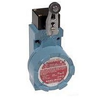
... Sensing & Control a Honeywell Division Installation Instructions Explosion Proof Heavy Duty LSX Limit Switches NON-PLUG-IN (Single-Pole or Double-Pole) PK 81181 MICRO SWITCH explosion proof switches are designed specifically for use in hazardous loca- tion applications. For a general description and classification of hazardous atmospheres refer to MICRO SWITCH Catalog 40. In addition to meeting explosion proof requirements the LSX meets additional liquid sealing classifications ...

Page 2

PK 81181 WIRING INSTRUCTIONS The circular cover on the front of the switch is unscrewed to expose the switching element for wiring or replacement. To aid in cover removal, a screwdriver or bar may be used on the wrench- ing ...

Page 3

... LSZ1A LSZ1A LSXA4L LSZ1B LSXB3K LSZ1B LSXB4L LSXC3K LSXZ1C LSXZ1C LSXC4L LSXZ1D LSXD3K LSXD4L LSXZ1D LSXE3K LSXZ1E LSXZ1E LSXE4L LSXZ1F LSXF3K LSXF4L LSXZ1F LSZ1H LSXH3K LSZ1H LSXH4L LSZ1JGA LSXJ3K-7A LSXJ4L-7A LSZ1JGA LSXZ1KHA LSXK3K-8A LSXK4L-8A LSXZ1KHA LSXL4M LSZ1L LSXM4N LSZ1M LSXN3K LSZ1N ...

Page 4

... PK 81181 PROPER APPLICATION OF LIMIT SWITCHES For limit switches with pushrod actuators, the actuating force should be applied as nearly as possible in line with the pushrod axis. IN CANADA: 740 Ellesmere Road, Scarborough, Ontario. INTERNATIONAL: Sales and service offices in all principal cities in the world. PK 81181 181 ...

Related keywords