TL-Q5MD1 Omron, TL-Q5MD1 Datasheet
TL-Q5MD1
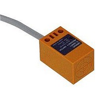
Specifications of TL-Q5MD1
Available stocks


Related parts for TL-Q5MD1


TL-Q5MD1 Summary of contents
Page 1
... Models are also available with 5-m cables. Add the cable length to the model number (example: TL-N5ME1 5M). *2. Models with robotics cables are also available. Add -R to the end of the model number (example: TL-N5ME1-R). Model Operation mode NO NC TL-Q5MD1 2M TL-Q5MD2 2M TL-N7MD1 2M TL-N7MD2 2M TL-N12MD1 2M TL-N12MD2 2M ...
Page 2
... Measurement conditions are as follows: standard sensing object, a distance of twice the standard sensing object, and a set distance of half the sensing distance. Applicable Sensors Provided with these Sensors TL-N5ME@, TL-N7MD@ TL-N5MY@ TL-N10ME@, TL-N12MD@ TL-N10MY@ TL-N20ME@, TL-N20MD@ TL-N20MY@ --- TL-N5ME@, TL-N5MY@ --- TL-N10ME@, TL-N10MY@ TL-N7MD@ TL-N12MD ±10 ±10 5 9.6 mm Iron, 30 × 30 × Iron, 40 × ...
Page 3
... VAC, 50/60 Hz for 1 min between current-carrying parts and case 2 10 times each 2 Destruction: 200 m/s 10 times each and Z directions IEC IP67 Approx TL-N/TL-Q/TL-G TL-G3D-3 7.5±0.5mm 10 mm Iron, 10 × 5 × 0.5mm 1 ms max VDC, ripple (p-p): 5% max max VDC (no-load) NPN transistor output 20 mA max. ...
Page 4
... E Models (DC switching models): A full-wave rectification power supply of 24 VDC ±10% (average value) can be used. TL-N10ME@, TL-N10MY ±10 Iron, 40 × 40 × times each and Z directions Approx. 170 g TL-N/TL-Q/TL-G TL-N20ME@, TL-N20MY ±10 Iron, 50 × 50 × Models Models Approx. 240 g 4 ...
Page 5
... Leakage Current TL-N@MY 2.0 1.5 1.0 Protective resistance mA AC power V 0.5 50/60 Hz Proximity Sensor (output OFF 100 120 140 160 180 200 220 240 260 Power supply voltage (V) TL-N@MY at 100 VAC Residual output voltage 100 100 VAC Residual load voltage OFF ...
Page 6
... Brass Aluminum Side length of sensing object: d (mm) TL-N12MD × Iron 10 8 Stainless steel (SUS304) 6 Brass Copper 4 Aluminum Side length of sensing object: d (mm) TL-N/TL-Q/TL-G TL-G3D 0 × Operate Reset Side length of sensing object: d (mm) TL-N5@ d × Iron 4 3 Stainless steel (SUS304) 2 Aluminum 1 Brass ...
Page 7
... Iron Stainless steel (SUS304) 4 Brass Aluminum Side length of sensing object: d (mm) I/O Circuit Diagrams DC 2-Wire Models Operation Model mode Non-sensing area Sensing object TL-Q5MD1 TL-N7MD1 (%) NO TL-N12MD1 TL-N20MD1 Non-sensing area Sensing object TL-Q5MD2 (%) TL-N7MD2 NC TL-N12MD2 TL-N20MD2 TL-N20@ d × Iron Stainless steel (SUS304) ...
Page 8
... NC TL-N10MY2 Load TL-N20MY2 Operation indicator (red) Timing chart Present Not present ON OFF ON OFF Proximity Present Not present ON * Load current: 100 mA max., TL-Q2MC1 Load current max., TL-Q5MC1 OFF ON OFF Present Not present Operate Reset High Low ON Proximity OFF Present Not present Operate Reset *1 ...
Page 9
... Dimension B is the same value as the value on the sides and the top. (The construction is symmetric around a point.) *2. The values for for the TL-N apply when there is metal on only one side of the sensor. If there is metal on two or more sides, the value must be multiplied by two or more. ...
Page 10
... Designing the Sensing Object for TL-G3D-3 Grooved Model For high-speed response to a toothed metal plate, the sensing objects must be at least the size of the standard sensing object and there must be sufficient distance between sensing objects. The response frequency for a toothed wheel like the one shown at the right is 1 kHz min ...
Page 11
... Insulator diameter: 1.9 mm), Standard length 1.5 9.3 0.5 * 18.1 0.5 3± 0.3 Toothed washer Lock nut M8 × 0.75 (slightly thin 4-dia. vinyl-insulated round cable with 3 conductors (Conductor cross section: 0.2 mm Insulator diameter: 1.2 mm), 29.8 Standard length Two, 4.3 dia Indicator *2 6 23.8 ...
Page 12
... Two 4 16± 22± 0.2 0.2 7 2.3 14.5 Applicable Models: TL-N10ME@ *2 Applicable Models: TL-N10MY @ Applicable Models: TL-N12MD@ *2 Material: Zinc-plated iron Y92E-N10C15 30 22± 0.3 Two, 4.3 dia. 13± 0.2 3.5 21 2.3 5.5 24.3 2.3 C15 conduit screw, JIS-B-0204 Applicable Models: TL-N10ME@ ...
Page 13
... Please read and understand this catalog before purchasing the products. Please consult your OMRON representative if you have any questions or comments. WARRANTY OMRON's exclusive warranty is that the products are free from defects in materials and workmanship for a period of one year (or other period if specified) from date of sale by OMRON. OMRON MAKES NO WARRANTY OR REPRESENTATION, EXPRESS OR IMPLIED, REGARDING NON-INFRINGEMENT, MERCHANTABILITY, OR FITNESS FOR PARTICULAR PURPOSE OF THE PRODUCTS ...