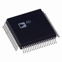
AD1843JS Analog Devices Inc, AD1843JS Datasheet - Page 29

AD1843JS
Manufacturer Part Number
AD1843JS
Description
IC CODEC STEREO 5V 16BIT 80PQFP
Manufacturer
Analog Devices Inc
Type
Stereo Audior
Datasheet
1.AD1843JS.pdf
(64 pages)
Specifications of AD1843JS
Rohs Status
RoHS non-compliant
Data Interface
Serial
Resolution (bits)
16 b
Number Of Adcs / Dacs
1 / 2
Sigma Delta
Yes
S/n Ratio, Adcs / Dacs (db) Typ
92 / 86
Dynamic Range, Adcs / Dacs (db) Typ
85 / 80
Voltage - Supply, Analog
4.75 V ~ 5.25 V
Voltage - Supply, Digital
2.85 V ~ 5.25 V
Operating Temperature
0°C ~ 70°C
Mounting Type
Surface Mount
Package / Case
80-MQFP, 80-PQFP
Available stocks
Company
Part Number
Manufacturer
Quantity
Price
Part Number:
AD1843JS
Manufacturer:
ADI/亚德诺
Quantity:
20 000
REV. 0
OVL1:0
res
LSS2:0
LMGE
LIG3:0
RSS2:0
RMGE
RIG3:0
Address 2
Data 15
Data 7
LSS2
RSS2
cleared to “00” after any write to this register. The peak amplitude as recorded by these bits is “sticky,” i.e., the larg-
est output magnitude recorded by these bits will persist until these bits are explicitly cleared. They are also cleared by
powering down the ADC left channel (see the ADLEN bit in Control Register Address 27).
LO; when the PWRDWN pin is asserted LO; or when the PDNO bit in Control Register Address 0 is set to “1” (all
conversions disabled).
ADC Left Overrange Detect. These bits record the largest output magnitude on the ADC left channel and are
00 = Greater than –1.0 dB underrange
01 = Between –1.0 dB and 0 dB underrange
10 = Between 0 dB and 1 dB overrange
11 = Greater than 1.0 dB overrange
Reserved for future expansion. To ensure future compatibility, write “0” to all reserved bits.
Initial default state after reset: 0000 0000 0000 0000 (0000 hex). Cleared to default when: the RESET pin is asserted
Left ADC Source Select
000 = Left Line Input
001 = Left Mic Input
010 = Left Auxiliary 1 Input
011 = Left Auxiliary 2 Input
100 = Left Auxiliary 3 Input
101 = Mono Input
110 = Left DAC1 Output
111 = Left DAC2 Output
Left ADC Microphone Gain Enable
0 = 0 dB Gain
1 = +20 dB Gain
Left ADC Input Gain. Least significant bit represents +1.5 dB.
0000 = 0.0 dB Gain
1111 = +22.5 dB Gain
Right ADC Source Select
000 = Right Line Input
001 = Right Mic Input
010 = Right Auxiliary 1 Input
011 = Right Auxiliary 2 Input
100 = Right Auxiliary 3 Input
101 = Mono Input
110 = Right DAC1 Output
111 = Right DAC2 Output
Right ADC Microphone Gain Enable
0 = 0 dB Gain
1 = +20 dB Gain
Right ADC Input Gain. Least significant bit represents +1.5 dB.
0000 = 0.0 dB Gain
1111 = +22.5 dB Gain
Initial Default State after Reset: 0000 0000 0000 0000 (0000 hex). Cleared to default and cannot be written to when:
the RESET pin is asserted LO; when the PWRDWN pin is asserted LO; or when the PDNO bit in Control Register 0
is set to “1” (all conversions disabled).
Data 14
Data 6
LSS1
RSS1
Data 13
Data 5
LSS0
RSS0
Input Control—ADC Source and Gain/Attenuation
Data 12
RMGE
LMGE
Data 4
–29–
Data 11
Data 3
LIG3
RIG3
Data 10
Data 2
LIG2
RIG2
Data 9
Data 1
LIG1
RIG1
Data 8
Data 0
RIG0
LIG0
AD1843


